


StefanATX
-
Posts
4 -
Joined
-
Last visited
StefanATX's Achievements

New Member (1/11)
0
Reputation
-
K2xx SUV Center Console Cooler Retrofit
StefanATX replied to 2003 SSEi's topic in Modifications & Accessories
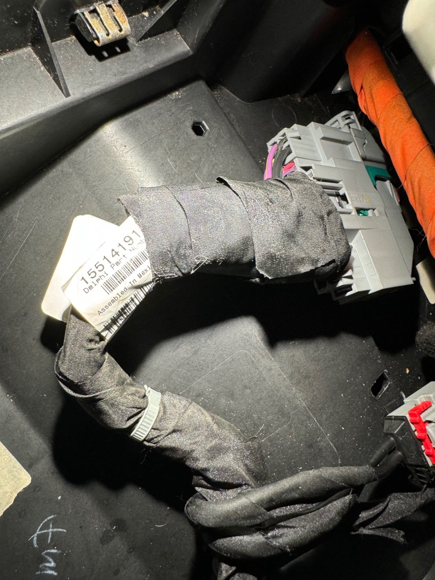
I use a WAGO clamp - that my grandfather invented. And wrapped the whole contraption. You can see that I used the white/brown wire from the original harness and inserted it into pin 28. This draws 12V and provides power to the cooler, the switch LED, and the backlight LED (backlight of the switch).
-
K2xx SUV Center Console Cooler Retrofit
StefanATX replied to 2003 SSEi's topic in Modifications & Accessories
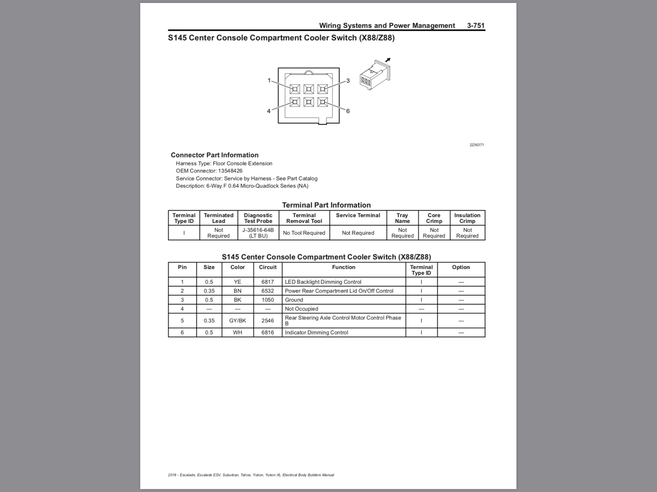
Switch connector pinout
-
K2xx SUV Center Console Cooler Retrofit
StefanATX replied to 2003 SSEi's topic in Modifications & Accessories
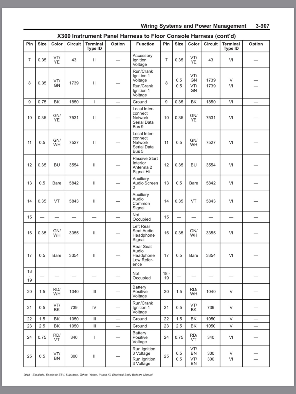
Harness connector Pinout
-
StefanATX joined the community
-
K2xx SUV Center Console Cooler Retrofit
StefanATX replied to 2003 SSEi's topic in Modifications & Accessories
I bought a center console cooler from an Escalate from eBay, including the correct wiring harness. The correct wiring harness for my 2016 Yukon XL Denali was 15514191 which came with the cooler that I got from eBay. I also bought the center console cupholder with the cooler switch built-in. it has its own wiring harness. There are harness versions with and without the wireless charger, and there are different versions of that charger for models 2015 and, 2016 and later. I found out the following pins from the Instrument Harness are not wired: Pin 6 (white) Indicator Dimming Control, Pin 41 (yellow) LED Backlight Dimming Control, and Pin 21 (violet/black) Run Crank Ignition Voltage 1. Pin 21 provides power to the cooler, while pin 6 drives the yellow switch LED, and ping 41 is the white backlight of the switch. Pin 6 and pin 41 are typically driven by the BCM (body control module). For simplicity, I connected all these pins to 12V, which means the backlight LED is always on, always at the same brightness, while the switch LED turns on when the cooler is on, also always the same brightness. (If you are adventurous, you can harvest these pins from under the dashboard. I am too lazy.) You could connect all these pins to pin 8 (violet/green), which is also the Run Crank Ignition Voltage 1, but I instead opted for connecting them to pin 28 (brown/white, but not populated in the harness) Inadvertent Power Control. This is normally connected by the center console light, and provides power up to 10 minutes after the engine was shut-off. This is more convenient, as it keeps the cooler powered when you stop briefly, for instance for gas. Otherwise, you need to remember to turn the cooler back on each time you turn off the engine. You need to remove pins 6, 21, and 41 from the new harness. You can purchase removal picks (you would need J-38125-11A, and J-38125-553), or you disassemble the connector, and remove the pins from the front. You need to remove the violet plastic inset, it has two clips on either side of the connector and pops out to the front. Now you can use a small screw driver from the front, the pin side, to lift the plastic latches that keep these pins in, and just push them out to the back - or you buy these picks. Switch Connector 1 - yellow -> 41 Console: LED Backlight Dimming Control (nc) 2 - brown -> 3 Cooler: Power Rear Compartment Lid 3 - black -> 23 Console: Ground 5 - grey/black -> 2 Cooler: Rear Steering Axle Control Motor Control 6 - white -> 6 Console: Indicator Dimming Control (nc) Cooler Connector 1 - violet/black - 21 Console: Run Crank Ignition Voltage 1 (12 VCC) (nc) 2 - grey/black - 5 Switch: Rear Steering Axle Control Motor Control Phase 3 - brown - 2 Switch: Power Rear Compartment Lid 4 - black - 3 Switch: Ground Btw, I have no idea why the switch ports 2 and 5 that connect to the cooler are named so weird. I have not measured or tested it, but these two wires are probably just NO (normally-open) wires of a standard switch, and PROBABLY can be shortened, if you do not have a switch. As I said, this is speculation from my side and needs verification, if you plan an install without a switch, or a different than the OEM switch.




-
Forum Statistics
250.4k
Total Topics2.7m
Total Posts -
Member Statistics
342,854
Total Members8,960
Most Online
-
Who's Online 7 Members, 0 Anonymous, 625 Guests (See full list)