


gopher206
-
Posts
6 -
Joined
-
Last visited
gopher206's Achievements

Enthusiast (2/11)
4
Reputation
-
Custom installation with Aux Upfitter Switch Bank
gopher206 replied to gopher206's topic in Modifications, Wheels & Tires
@mjonesjr84 here you go... Switches.pdf -
Custom installation with Aux Upfitter Switch Bank
gopher206 replied to gopher206's topic in Modifications, Wheels & Tires
will do...give me a day or so to come up with something...thanks! -
Custom installation with Aux Upfitter Switch Bank
gopher206 replied to gopher206's topic in Modifications, Wheels & Tires
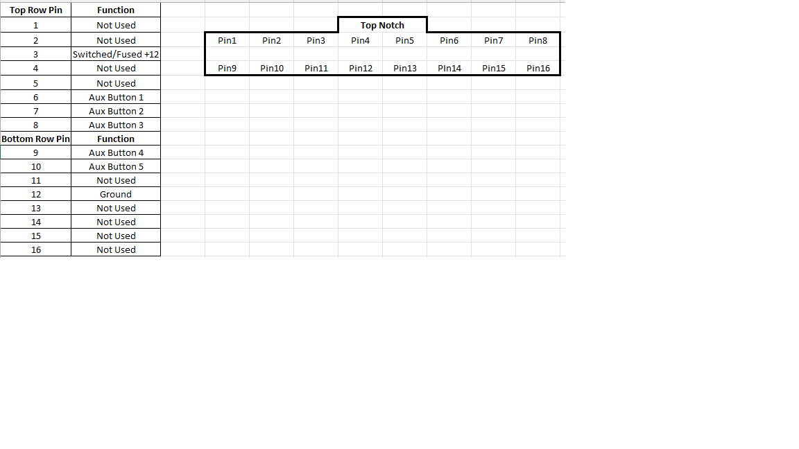
So for the pin 3 power, I tapped off the available exposed pin in the passenger fuse box that is switched when the ignition is on. Crimp connector on that pin does the trick. I did put an inline 7.5amp fuse as a safety measure. Two wires split off this exposed pin, one for pin 3 and then the other wire thru the firewall to the 85 or 86 pin of the relays. This is the +12v you need for each relay so that when you press each aux switch, it will complete the circuit with the ground connection. Pin 3 wire and 5 more wires to the aux switch bank are for the outputs to relays that I mounted under the hood. The pin 12, I grounded to the frame of the center console to a metal stud under it. The bank passes ground when the switches are pressed so there is little load on them (as long as you are only tripping relays). Pin 3 lights up the led on each switch when pressed. I found relay banks online thru ebay and amazon. Most come with clear or protective covers and once you run your 5 wires thru the firewall grommet for each switch, you then have the switch connection for the 85 or 86 pins on the coil of the relay. So for all of this, all switches will function only when ignition is on. For me this ensures I don't leave anything on when i leave the vehicle. If you don't want the switches to require the ignition to be on, don't wire pin 3 to that fuse box stub pin but instead to a fused constant +12 and then also to either 85 or 86 pin of each relay. I can prob mock up a wiring schematic if that helps anyone. -
Custom installation with Aux Upfitter Switch Bank
gopher206 replied to gopher206's topic in Modifications, Wheels & Tires
Very welcome, silveradosid! -
Custom installation with Aux Upfitter Switch Bank
gopher206 replied to gopher206's topic in Modifications, Wheels & Tires
Thanks Bikerjon! Appreciate it! -
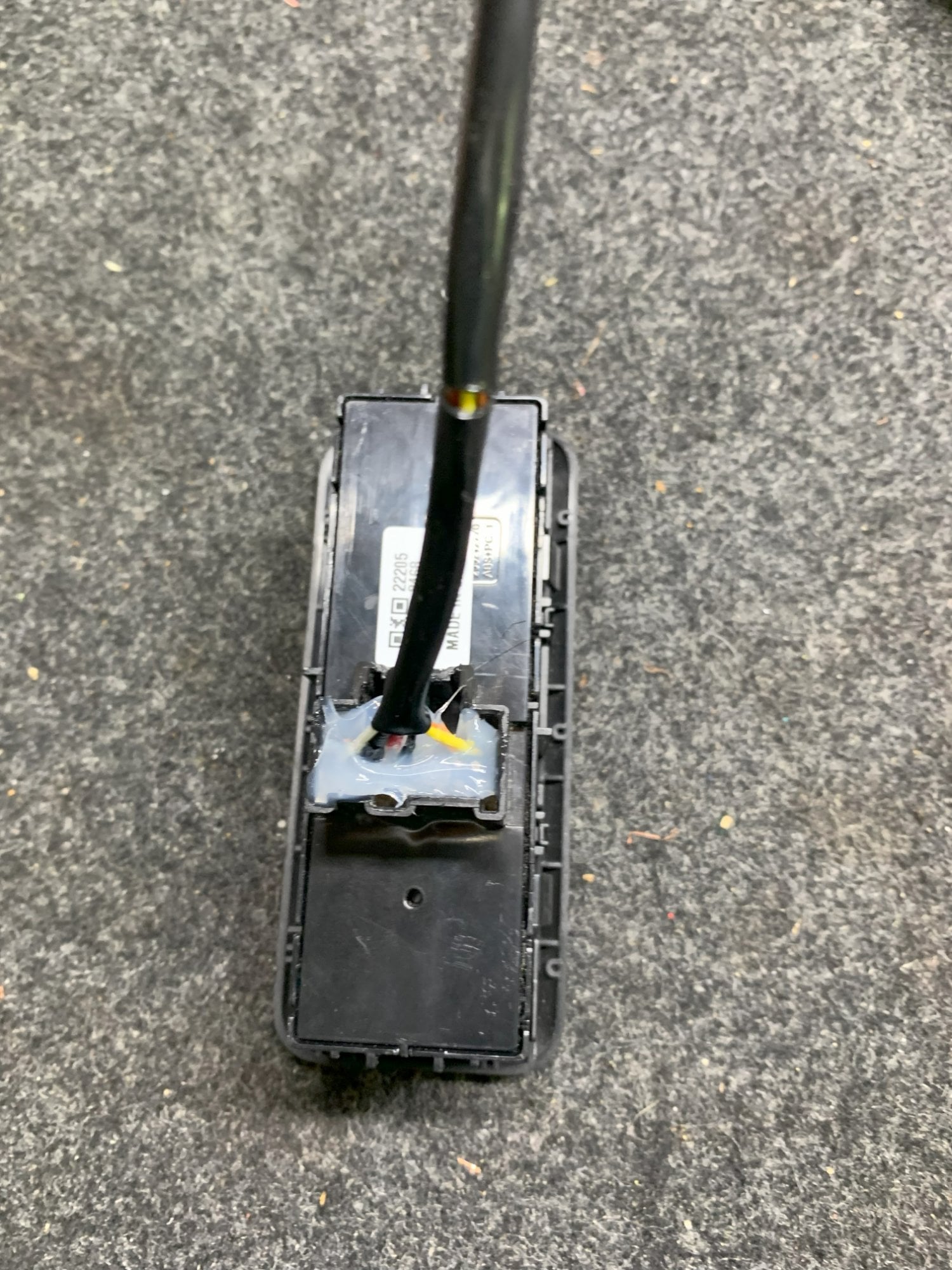
As the owner of a refreshed 2023 Silverado Z71, I didn't want to buy the entire dash panel for the upfitter auxiliary 5 button switch bank install that I am finding videos on everywhere. I hope this helps others that don't want to spin the money on that integration but would rather custom use the switches for your own needs. The switches provide Ground when depressed so they can be wired to Bosch style relay pin 85 or 86 for your needs. Here is the pinout and some pics of where I placed my switches. Hope this helps others out there that are looking for DIY options. For the wire leads, you can order a custom connecter but they want $100 for it. I used the pin header cables from an old PC tower. The same pin headers that are used for reset, power, led, and reset that attach to a motherboard and they attach perfectly. Added silicone to it and it sealed it up nicely. When depressed, the amber led on each light up and that is from pin 3 being powered with switched/fused +12v. The bank is installed on the drivers side, left side of the console. The console underneath is hollow so cutting with a Dremel tool does the trick. It is out of the way, concealed and does not require dash panel replacement.





-
Forum Statistics
250.5k
Total Topics2.7m
Total Posts -
Member Statistics
342,926
Total Members8,960
Most Online
-
Who's Online 9 Members, 1 Anonymous, 1,230 Guests (See full list)