


SwitchBladeSierra
-
Posts
14 -
Joined
-
Last visited
SwitchBladeSierra's Achievements

Enthusiast (2/11)
6
Reputation
-
UPDATE 3: Supposedly you need any cluster OTHER THAN a WT model cluster to have full steering wheel functionality. Went back to the part truck and removed the all terrain cluster, trim, and snipped as many wiring harnesses as possible to pull out the factory terminal leads if needed that poor donor truck… As of right now I’m relying on Darth_Vader’s thread and YouTube videos. will update.
-
UPDATE 2: Steering wheel control backlights and control of the cluster can supposedly be achieved by adding a wire to pin 20 of the cluster and tapping it to pin 2 of the main clock spring harness. I'm going to give it a shot - will update
-
UPDATE: Part Numbers Heated Steering Wheel: 23278632 Clock Spring: 23193462 Removed the heated steering wheel but left the clock spring in - Installed my original steering wheel to the new clock spring to see if the back lights work, and they do... Confused to the max. At this point, I think my game plan is to remove the switch assembly on the new steering wheel that manages the cluster and 3D print a blank insert to go in its place. As to the heated steering wheel portion - I will reinstall as I had it, where it was receiving constant power and not shutting off, but this time will add a switch in line and mount it near the head light knob. I'm done messing around with wiring and what not. Lesson learned - never buy a base model vehicle... Nothing but trouble when trying to customize or add higher trim upgrades. Honestly ridiculous.
-
Howdy folks, Recently I pulled a heated steering wheel and clock spring out of a 2015 Sierra All Terrain (part numbers coming soon - will have to disassemble), and just installed it on my 2016 Sierra WT (as base model as it gets). On install, I noticed that I’m missing the connector often tucked behind the dash for the heating element. No problem… or so I thought. I used an “Add-A-Fuse” at my heated steering wheel fuse location, which has voltage, but no wires. I ran it to the positive of the heated steering wheel (Violet/White), and took black to ground. Hooked up the battery, turned the truck on - no heated steering wheel. No button backlights. Was pleased to see that my cruise control was working though. Read a post suggesting reversing polarity, so I gave it a shot. Violet and White to ground, Black to power. Aha! Heat! But I seemingly can’t turn it off AND still no backlights on any of the buttons. Checked all fuses, everything is still in good order. I’m stumped. Does anyone have any insight? If so, please share!
-
Heated steering wheel
SwitchBladeSierra replied to Dennisfiremanny's topic in 2014-2018 Silverado 1500 & Sierra 1500
I’m praying that someone sees this and can help me out… pulled a heated steering wheel and clock spring out of a 2015 Sierra All Terrain, and just installed it on my 2016 Sierra WT (as base model as it gets). On install, I noticed that I’m missing the connector often tucked behind the dash. No problem… or so I thought. I used an “Add-A-Fuse” at my heated steering wheel fuse location, which has voltage, but no wires. I ran it to the positive of the heated steering wheel (Violet/White), and took black to ground. Hooked up the battery, turned the truck on - no heated steering wheel. No button backlights. Was pleased to see that my cruise control was working though. Read a post suggesting reversing polarity, so I gave it a shot. Violet and White to ground, Black to power. Aha! Heat! But can’t turn it off AND still no backlights. Checked all fuses, everything is still in good order. I’m stumped. Does anyone have any insight? If so, please share! -
Update for anyone following: Installed everything as shown in diagram. Opted for 8 AWG from Battery Positive to a 50A resettable inline breaker. 8 AWG is tied into to 2x 12 AWG wires feeding a 6 way fuse bus in parallel (manufacturer’s design of what I purchased). 4 of the 6 fuses available for circuits are tied to terminal 30 of each relay. I tied a jumper from one of my spare circuits off the bus to terminal 86 of each relay. The trigger, terminal 85, was pulled from my interior by way of T-Taps from the X61A-X5 pins 10, 11, 17 and 23. This was the hardest part of the job. Even with the X61A unbolted and the X5 removed - there was VERY little wiggle room. I added back up lights that I want to come on with my cargo lamp - but when I would check continuity between S48A-X1 pin 18 to its respective landing point on the X61A-X5 it triggers the factory relay… Instead I opted for a add-a-fuse on the passenger interior fuse panel (fuse location 10 - cargo lamp) and ran it through the boot on the driver side to my load. Did this to avoid introducing any electrical gremlins. Note: Please check for continuity between the S48A-X1 and the X61A-X5. In my case wire colours were not the same as other’s who have posted. To do a continuity check you need a Multimeter. Completely disassemble the S48A-X1 and remove the brown face plate off the X61A-X5 by way of a flat head screwdriver - this was the only way I could get any results. The outputs, terminal 87 of the relays, were fed into a junction box and landed at Individual studs and were labelled Aux 1-4. At this point, all you need to do is run wire to your loads and bring them to ground. I created a negative bus in the engine bay, all my negatives land here. For anyone having issues with all of your new aux switch lights coming on with the press of one - I noticed this only to be an issue when the battery wasn’t hooked up to my relays? No idea why, but it was quickly corrected by having my system buttoned up and functional.

-
HELP! DUMPING COOLANT
SwitchBladeSierra replied to SwitchBladeSierra's topic in Troubleshooting & Recalls
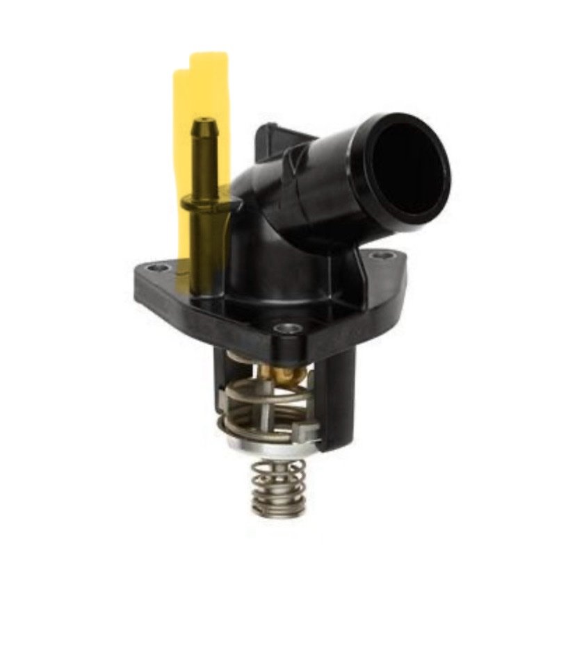
If anyone lands here looking for an update - the problem wasnt with the hose, the clamp, etc... I purchased a metal Thermostat housing that just must not of been made to spec. It just wouldn't plug up the hose.. Went back to a plastic cheap housing - leak fixed. Some plumbers tape carefully placed in tandem with a clamp likely would've gotten the job done. Best, -
For anyone following, this is what I have deduced from this forum - and my very specific niche case. Please do let me know if you see me going in the wrong direction here. For context, I have a 16 sierra 1500 w/t. Has TC and Cargo light switches. Removed the switch to find the X1 and X2 of the S48A connection populated with wires (x1 10-14, and x2 1-5). Took photos of the X61A-X5 to find the wires from S48A-X1 land here at their respective pins (10, 11, 17, 23 on the X5). Was hopeful that this means my X51A fuse box has the appropriate pins... No cigar. So now I will be routing wires from the rear of the X61A-X1 to the engine bay and to their respective negative relay triggers. Please see to the diagram. If any has insight as to where the S48A-X2 pins 4 and 5 land that would be awesome. Will be attempting this sometime shortly and will likely make a youtube video out of it. Note: please disregard fuse sizes. Main fuse will likely be 25A, all mini bus fuses will likely be 10-15A. Here is my parts list: GM 84347199 - TC, Cargo Light, Exhaust Brake (useless to me unless I find a means to reconfigure), Aux 1 - 4. 12V 6 Way Pre-Wired Fuse Relay Box Kit with 4 x 40A 4-Pin Relays (link below - some mods required to make negative trigger) https://www.amazon.ca/dp/B0F4KCS43B?ref=ppx_yo2ov_dt_b_fed_asin_title&th=1 Various wire sizes (12 AWG - red and black, 14 AWG, 16 AWG multi-colored bundle) Wire termination leads for X61A-X1 (unknown at this time) Crimp connectors/Soldering Gun Heat Shrink Split Wire Loom To be continued... Cheers
-
Hello, wondering if anyone can help me with this little problem. I was trying to order the Upfitter Switch that has TC, Cargo Light, Blank, Aux 1-4.... Order was cancelled due to "not having it". The only available option to me now is the Upfitter Switch that has all these options, but in the blank space there is "Exhaust Braking". My truck is a gasser, so this is of no use to me. I need to find where Pin 4 and Pin 5 of the X2 connector run to (i.e X61A - X1 - Pins X & Y), and manipulate that somehow to get my desired outcome. Has anyone done this? Would there be any implications with me just doing nothing with it and installing it as is and never using it? I have gathered that it is "momentary" - so there are some considerations there. Please help!
-
HELP! DUMPING COOLANT
SwitchBladeSierra replied to SwitchBladeSierra's topic in Troubleshooting & Recalls
You’re good at this. Thank you, you might be on to something with screw clamps for the win. when I got home yesterday the screw clamp came loose somehow, either from heating cycles or whatever I don’t know. But I tightened her down good again and surprise, it stopped the leak. Will continue to monitor it, I’ll avoid using those constant tension clamps I just bought if I can. Get some schmoney back… thank you for all your help, wishing the best -
HELP! DUMPING COOLANT
SwitchBladeSierra replied to SwitchBladeSierra's topic in Troubleshooting & Recalls
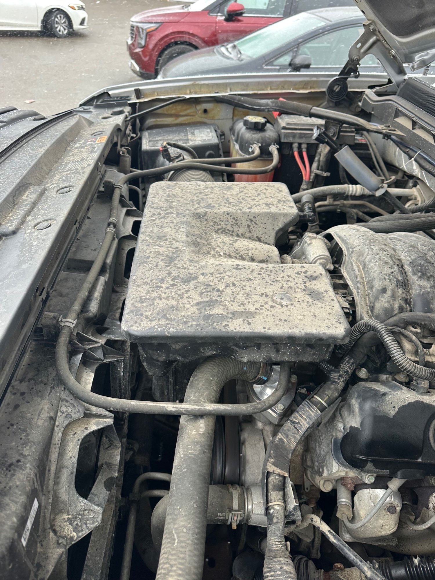
Here are some photos boss, looks like a return path to the reservoir.
-
HELP! DUMPING COOLANT
SwitchBladeSierra replied to SwitchBladeSierra's topic in Troubleshooting & Recalls
Hey man thanks for replying, I cant understand why it’s being such a ####. I thought of cutting the hose and having fresher rubber to work with, but I got cold feet. that’s almost identical to the clamp I used yesterday, again, it worked at first, but after my 15 minute commute to work this morning I popped the hood and coolant was sitting on top of the thermostat again. I just bought an assorted pack of (probably cheap and trash) constant tension clamps. Hoping for the best. Maybe I’ll use a combination of those and the clamp I already installed. I’ll update when I get to it, best -
Hello, I recently swapped out my thermostat and, for the life of me, cannot get the smaller of the two hoses going to the thermostat to seal. the factory spring clip wasn’t working, so I swapped it out and temporarily fixed it with a clamp you have to manually tighten with a hex socket or flathead (not recommended for this use case). However, 1 day later it’s already leaking again. Does anyone know: - the size of the (smaller) hose going to the nipple of the thermostat - the correct size clamp for this hose i would measure myself but I’m stuck at work and cannot do anything for the next 10 hours.. Options are limited at Canadian tire and Home Depot.



-
Forum Statistics
250.6k
Total Topics2.7m
Total Posts -
Member Statistics
342,992
Total Members8,960
Most Online
-
Who's Online 5 Members, 1 Anonymous, 720 Guests (See full list)