

tha_lildude
-
Posts
8 -
Joined
-
Last visited
tha_lildude's Achievements
")
Enthusiast (2/11)
15
Reputation
-
@MNorby Sorry for the delayed response. No extra bcm programming necessary. I haven’t even checked to see if the circuit for battery or ignition fuse location was operable or not. Both of mine were placed in the 12v constant location. I can check tomorrow and I’ll add on this post my results.
-
Yes. I had to extend them a bit but they ran through the firewall, into the fuse block and another small *wire was put into the connectors that the fuse block plugs into. There should be pictures of where the wires run into but I had taped it all back up before I took pictures so I cant say for sure exactly what pin number it is but if you look at the pictures you can see the small *wire run into the junction connector that the fuse block plugs into.
-
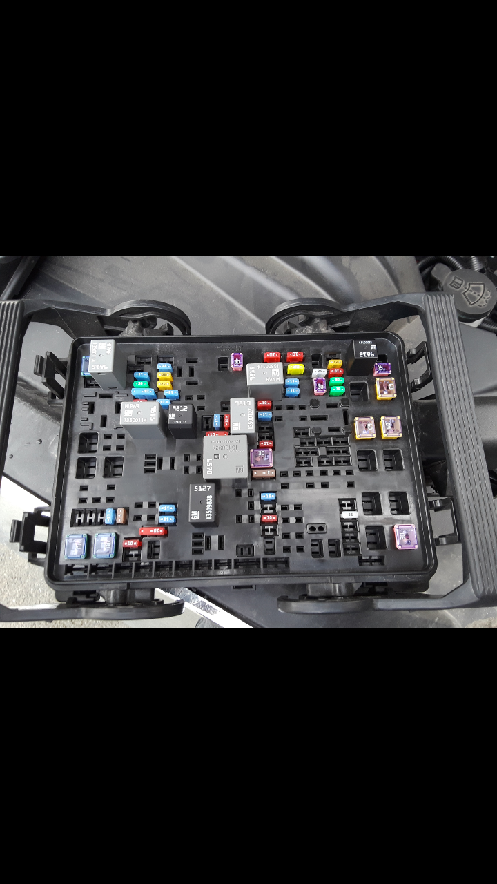
Two fuse block tops compared. Relays circled. One is for a second fuel pump and the others are for aux. Fuses pertaining to aux are there but not identified. You can tell from comparing though.

-
Pictures of new and old Underhood fuse block. On the new block, red indicates trigger wire, or wire that will go from junction connector to red marks. Blue marks are the output power to whatever you want to be powered. Blue is big *Wire and red gets small *Wire. Do your due diligence and ensure they are correct! I do not remember 100% if these were the ones I used but I do believe I did. But again, test to ensure.
-
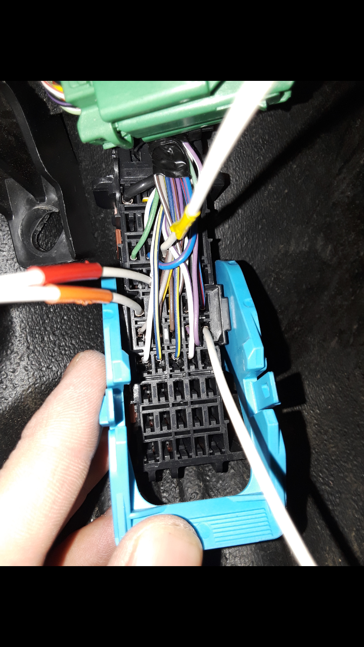
Rear of junction connector. This is where I inserted four of the small *Wire. I found continuity from front to back of junction connector. Remove three 10mm nuts to pull up junction box for better access. Note tape colors on wires, and one not color taped.
-
Inside driver junction connector by brake pedal. Bottom right connector. Be careful because there are multiple yellow/white and white/blue. I don't remember exactly if there are other multiples but test continuity from the wire to the wire behind the AUX switch. Then test continuity from front of junction box to rear of junction box.
-
I will get some and put them up soon.
-
I have just successfully fully integrated my AUX switches OEM style. My fuse block did not come with the relays or fuses, nor did it have connectors for them. I had to purchase a few new things. Underhood Fuse Block - Part #84075778 Price $208.50 Aux switches - Part #23145158 Price $73.21 Wire - Part #13578892 Price $9.93 Qty. 4 Wire - Part #13575832 Price $9.93 Qty. 8 Yes I know this was expensive but it is now pretty much completely OEM. I did have the wiring that came out of the back of the original switch. The four wires that correspond with the aux switches are Red/White - Aux 1 Yellow/White - Aux 2 Green/Gray - Aux 3 White/Blue - Aux 4 (I forgot which color this was but on a diagram I have it says WH/BU) The wires run down to the big junction box near the floor and brake pedal. They run into there but they do not come out the back. They run into the bottom right connector and there is continuity to terminals on the back. You will need to test them. Get your continuity tester, one lead goes on the front and the other, start touching all of them on the back. You then get *Wire and insert it into the junction connector that corresponds to the continuity you tested for. I used a different color tape on each wire as I plugged them in so I knew which was aux 1, 2, 3, and 4. You will need to pull up the top little plastic piece on the junction connector to insert the wire. The new *Underhood Fuse Block changes in reference to the one my truck came with were four auxiliary fuses and relays, and a second fuel pump fuse. Here is where it is a little tricky but I will do my best to explain. You will need to remove your fuse block. On the underside you will see a few pins are different. On one of the connectors, it will be different due to the second fuel pump connector (no wire is ran to it though). The two others ones that are different are the middle one toward the firewall side of the truck, and the firewall driver fender side. Those are the only two you need to get into. Pull the junction connector up (there is a tab that you push, you then slide the connector toward the firewall about a 1/2" then it'll lift out) Undo the tape, cut the zip tie (if necessary, but replace it) and then pull off the underside cover to access the holes to insert the pins from the *Wire. I can't explain how to get it off but if you got this far, you will figure it out and don't break it, its easy to come off once you figure it out. Back to the Fuse block. **Pay attention or you will wire it wrong** What I did was slightly lift the relays and you will need to test each of the four leads for continuity. One will have continuity to the fat spade (This one feeds hot to the whole junction connector) and this corresponds to 30. You will find two medium spades that correspond to 87 and to 85. You will find a small spade corresponds to 86. You will plug in your big *Wire to the medium spade that corresponds to 87 that is ALSO different then the original fuse block. Your new fuse block will have the spade, your old fuse block will not have the spade. If this is true, this is the one you will insert the medium *Wire into the junction connector. You do this for all four relays. You also need to test continuity for 86 and a small spade and again, your new fuse block will have the small spade, your old one will not. There are two small spades and one big spade in the junction connector closest to the fender and firewall. The rest go in the middle toward the firewall. Now you have all of your connections made, you need to connect the small *Wires together. Make sure you mark the wires (I used different colored tape) that correspond to the relay that activates aux1, 2, 3, and 4. I also put a little tape on each relay so I wouldn't forget which tape meant what. I soldered on a roughly 16" piece of wire to the small *Wire and punched it through the rubber grommet that is on the firewall. There is a little nipple looking piece that sticks out, I cut a small X and pushed the wires in. Attach those to the wires you plugged in inside the truck in the junction connector. Now all you have to do is install your switch and plug your lightbar, caution light, backup light, or whatever it is you want to the big *Wire and it will provide power to it. I hope this helps someone. The dealer, two of them face to face, and two of them that I called mentioned it couldn't be done OEM. I do car electrical daily so I knew better. One explained the BCM will throw codes especially if the truck doesn't have plow prep blah blah blah. None of this runs through any voltage monitoring. That's all nonsense and was their excuse for being lazy. Document 110L states it can't be done as well. It can, it's just expensive.


-
Forum Statistics
250.4k
Total Topics2.7m
Total Posts -
Member Statistics
342,822
Total Members8,960
Most Online