

TinkeringFox
-
Posts
105 -
Joined
-
Last visited
-
Days Won
3
Content Type
Profiles
Forums
Gallery
Events
Articles
RPO
Store
Blogs
Everything posted by TinkeringFox
-
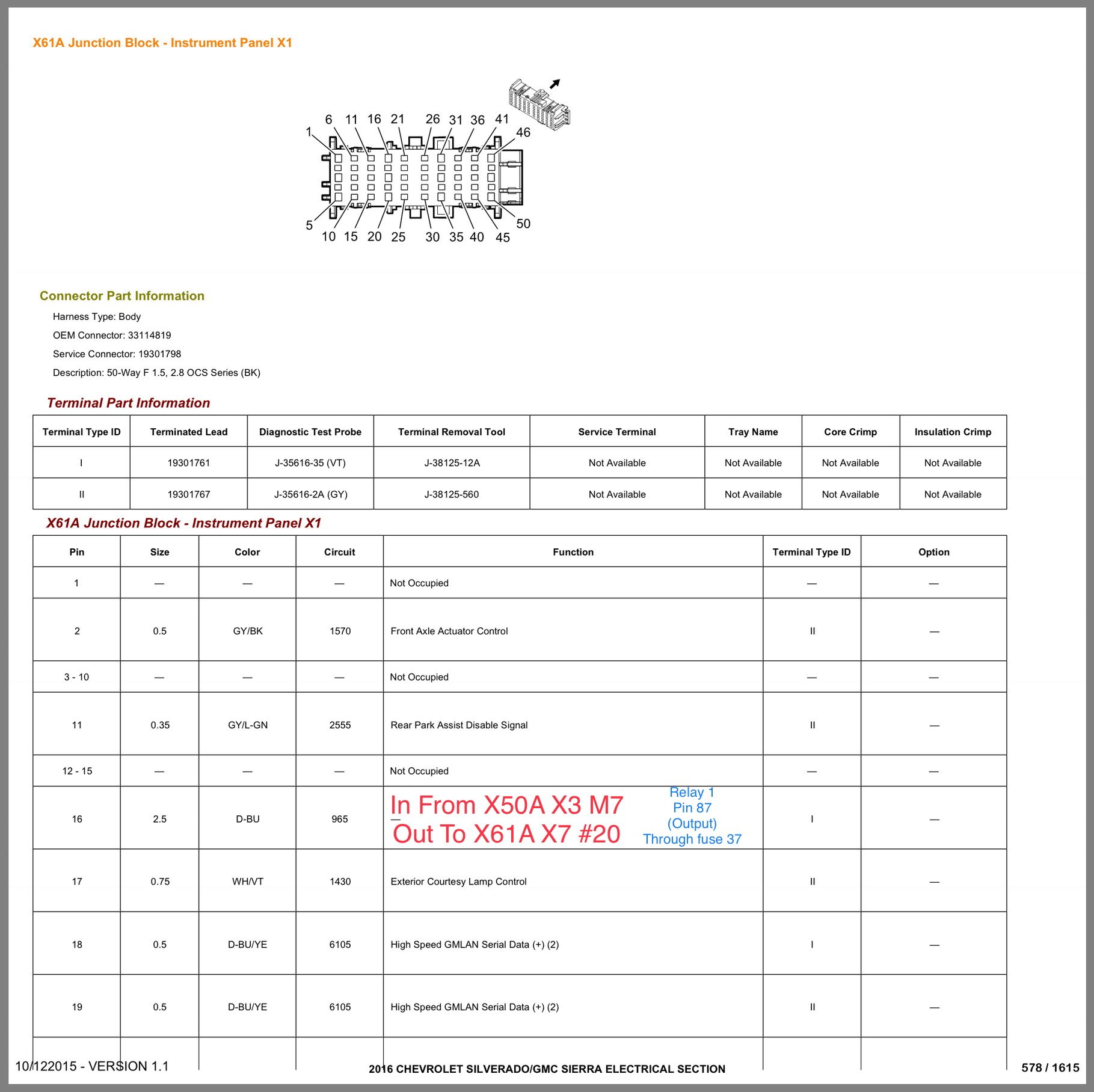
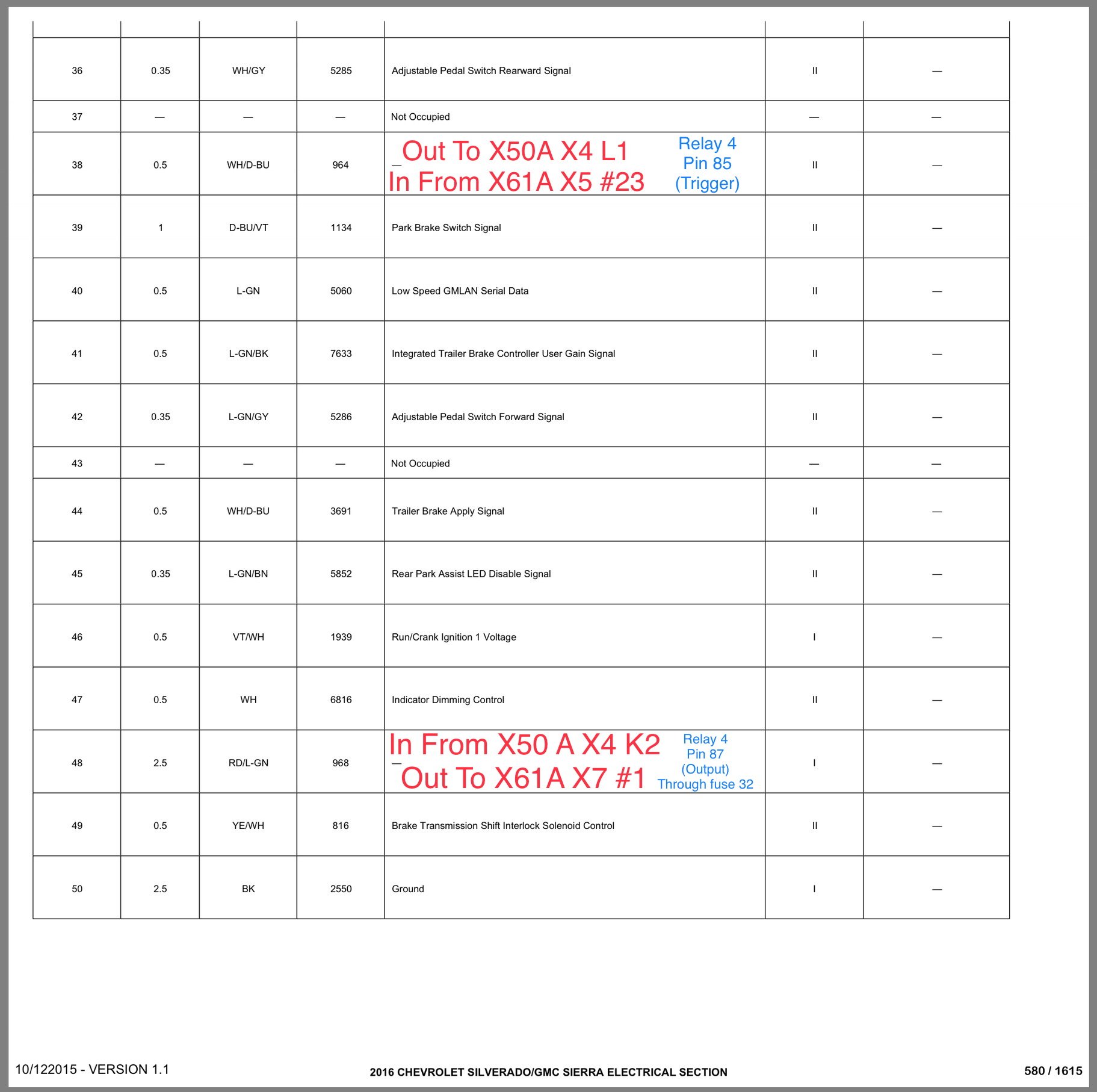
The OEM wire routing would go from the S48A (switch panel) to the X61A, X4connector(Junction box behind brake pedal) then out of the X61A, X1 connector, and into the X50A, X3 & X4 connectors (under hood fuse box) your accessory power or output from the relays will come out of the X50A (fused) and back into the X61A, X1 connector and out of the X61A, X7 connector. These pictures show the routing in and out of the X61A junction block behind the brake pedal. Please note: in Gm Upfitter there is a discrepancy between 2015 and 2016 model years pertaining to where the wires from the S48A (switch) land at the X61A (junction box). They land in either Connector (X4 or X5). Simply verify by checking the location and color of neighboring wires to be sure you’re on the right connector. This may be due to a type-o or different wiring on different model years. .......still sorting that out.

-
Sorry, just read you only have TC, Cargo, Aux1-4 On the same page now
-
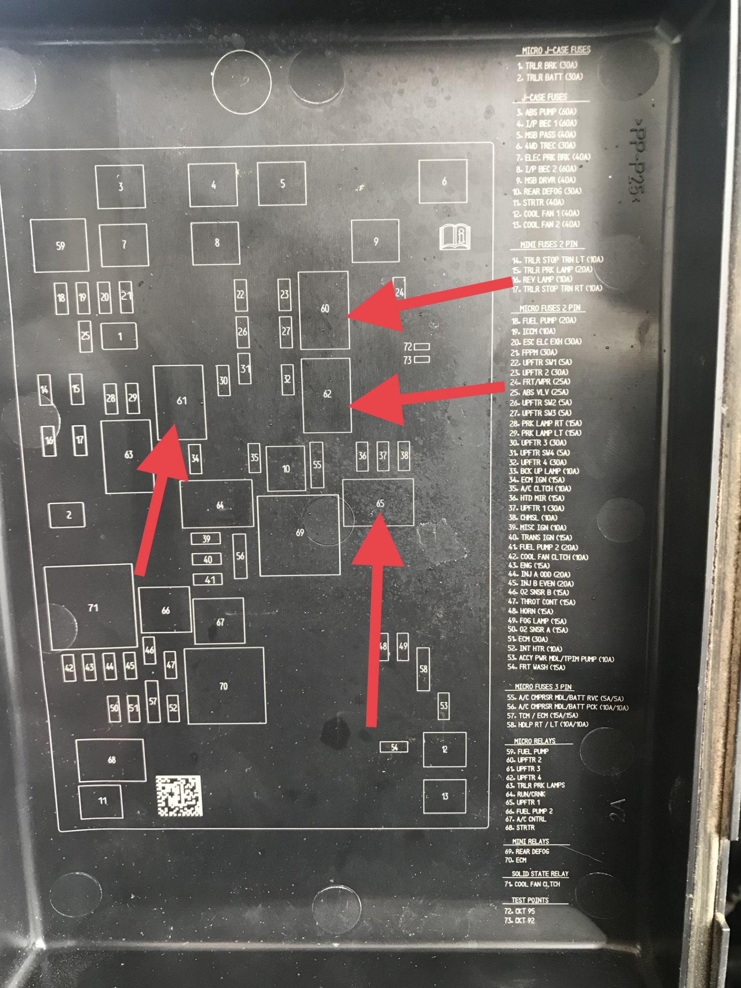
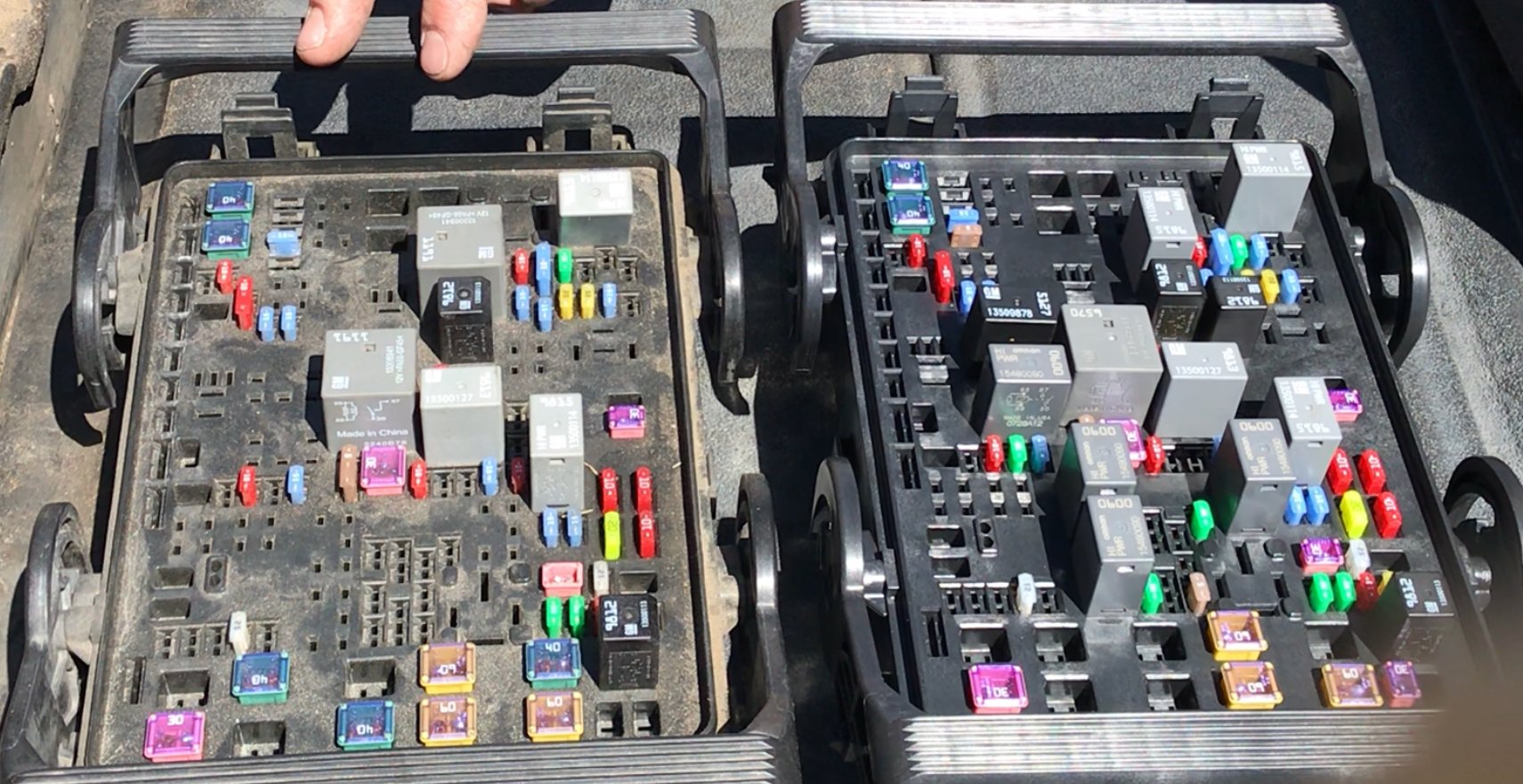
@WesternMike can you snap a picture of your underhood fuse box, specifically where Upfitter relays 1-4 would plug in. (#60,61,62,65) I want to see if the pins are present for the relays. ( if it’s just a blank cavity or if there’s a metal pin inside to contact a relay)
-
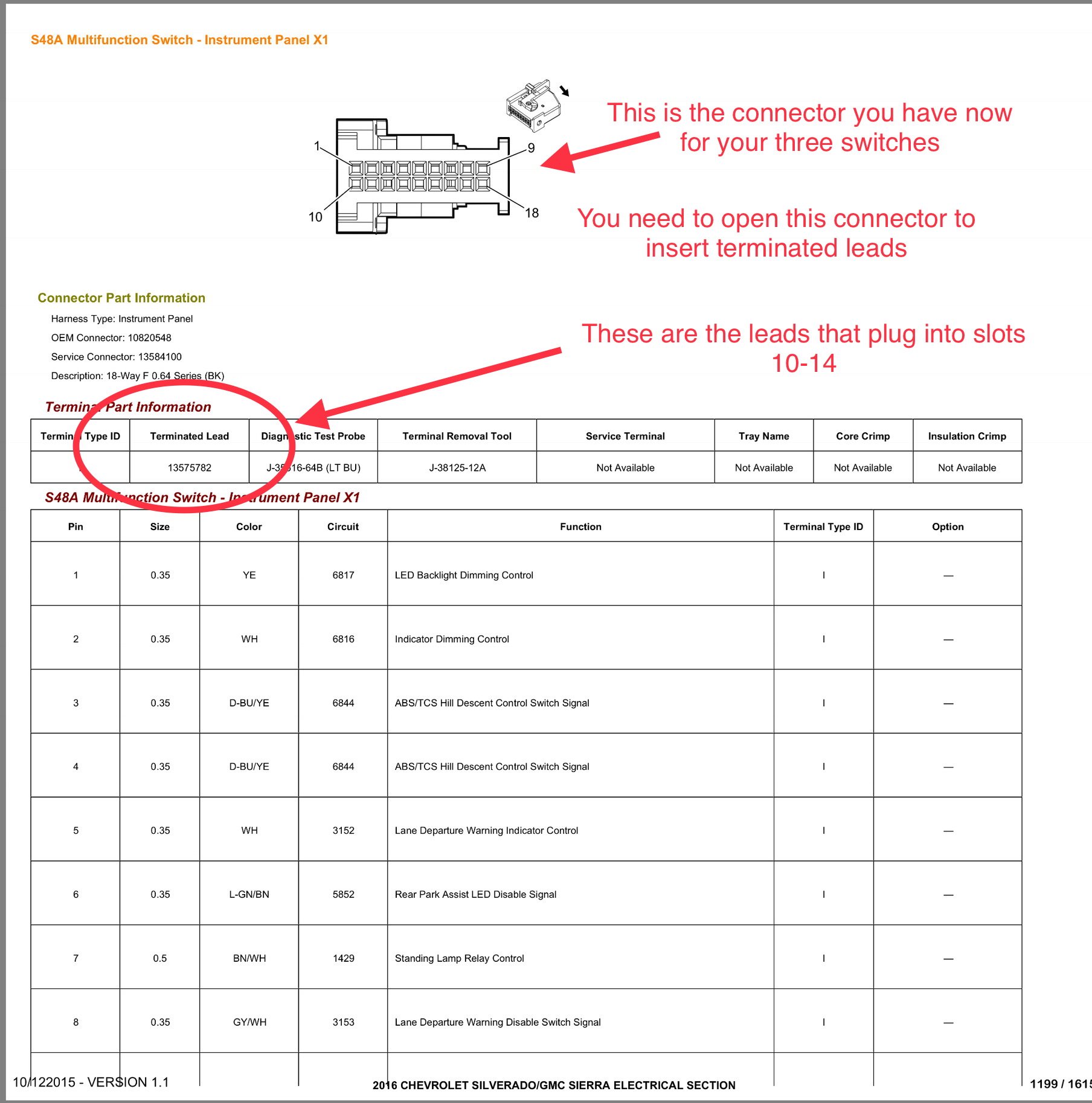
Ok, this is good! Pins 10-13 are already wired so you’re in luck. These wires go to the X61A junction block behind your brake pedal on the firewall. They plug into the X61A-X5 connector (on the lower right) and come out the (X61A-X1 connector (firewall side behind X5) from there they go up to the under hood fuse box (X51A).
-
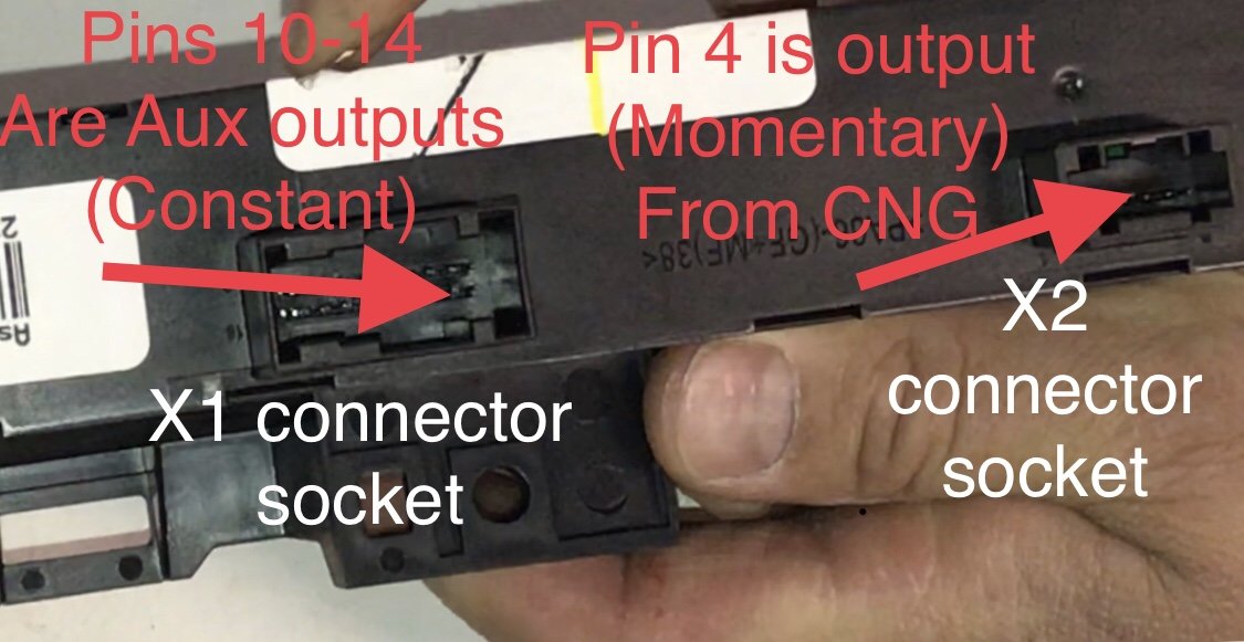
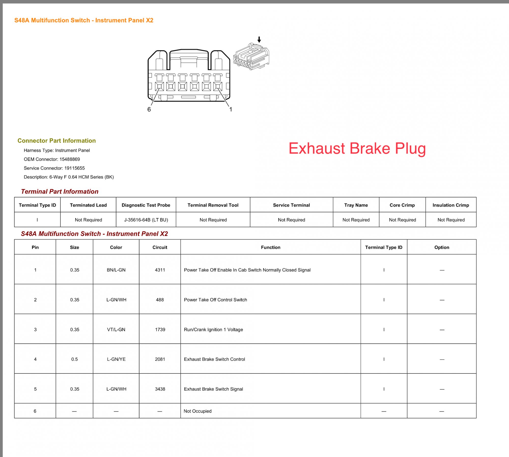
@csjumper2003 The TC & Cargo wires stay where they are. on the plug for the X2 connector you would cut the wire for pin number 4 to run to your air horn relay. You don’t necessarily have to cut the wire from #4 meaning you can just strip back some of the insulation and attach another wire to it. This wire (X2 #4) is the signal wire from the CNG switch. This plug that is there at the X2 connector is not doing anything in your application. It should have 6 wires in it and they aren’t doing anything so yo can use them (at least the one going to X2 #4) without worry. The link I provided is for a wire with a terminated lead meaning it’s a wire about 1.5 feet long with the terminal needed for the X1 connector factory crimped on the end of it. (Pigtails) (order 4 of them) you can open up your X1 plug and insert these wires directly into cavities 10,11,12,13 and then close the plug back up. Your X1 plug will then plug back in to the X1 opening with 4 new wires coming out (from Aux 1-4). These are your constant on/off negative signals from Aux 1-4.
-
I assume your truck has a gas motor? if so then the X2 plug doesn’t need to be used. I’m guessing you got the upfitter switch with TC,Cargo, Aux 1-4? does your X1 harness have any wires coming from pins 10-13?
-
Here is the back of your new “Upfitter Switch” from eBay. The smaller socket (X2) is where the Exhaust Brake or CNG plug if you had that would plug into. Although you never had either of those options you may very well have the harness sitting there plugged into a blank socket in the X2 position. You can plug this harness into the new “Upfitter Switch” from eBay and use the wire that goes to pin number four in that X2 connector. PIN number four in the X2 connector is the one coming from the CNG button and it is a momentary negative signal. This can be used to trigger a relay for your air horn since it only sends a signal while you’re pressing the button. The other switches send send their signal through the larger X1 connector (18 position). Pins 17&18 are your traction control signal and your cargo lamp signal. (Both are momentary negative signals) These signals go to the BCM and tell it to do what it does. Your ”Upfitter” or “Aux” switches use pins 10 through 13 (10,11,12 &13). These switches send their constant negative signals through these pins. Your harness that is plugged into X1 will likely not have any wires occupying pins 10-13. You will have to add these wires (13575782) https://www.gmpartsdirect.com/oem-parts/gm-f--s-wire-13575782 these wires can be used to trigger 4 different relays in your under hood fuse box X50A or 4 relays from BFE Amazon or eBay wherever. They send a negative signal until you press the button again.
-
Yes, all of the signals are negative. If you install the upfitter switch with the CNG or Exhaust Brake you’ll forget about the HDC and just grab that power from X2 cavity 4.
-
Yes, the momentary would work for that. You could also open one of the Auxiliary switches and remove the little “j” shaped spring and make it a momentary switch. I’ll take a picture of that next time I get to the work bench. It’s pretty easy though.
-
Um, yep....that’s exactly what was just done on page 13.
-
I’m not sure if that combination is an option but you can get it to work using 23145163 or 23146445. You’ll just to do a little wiring.
-
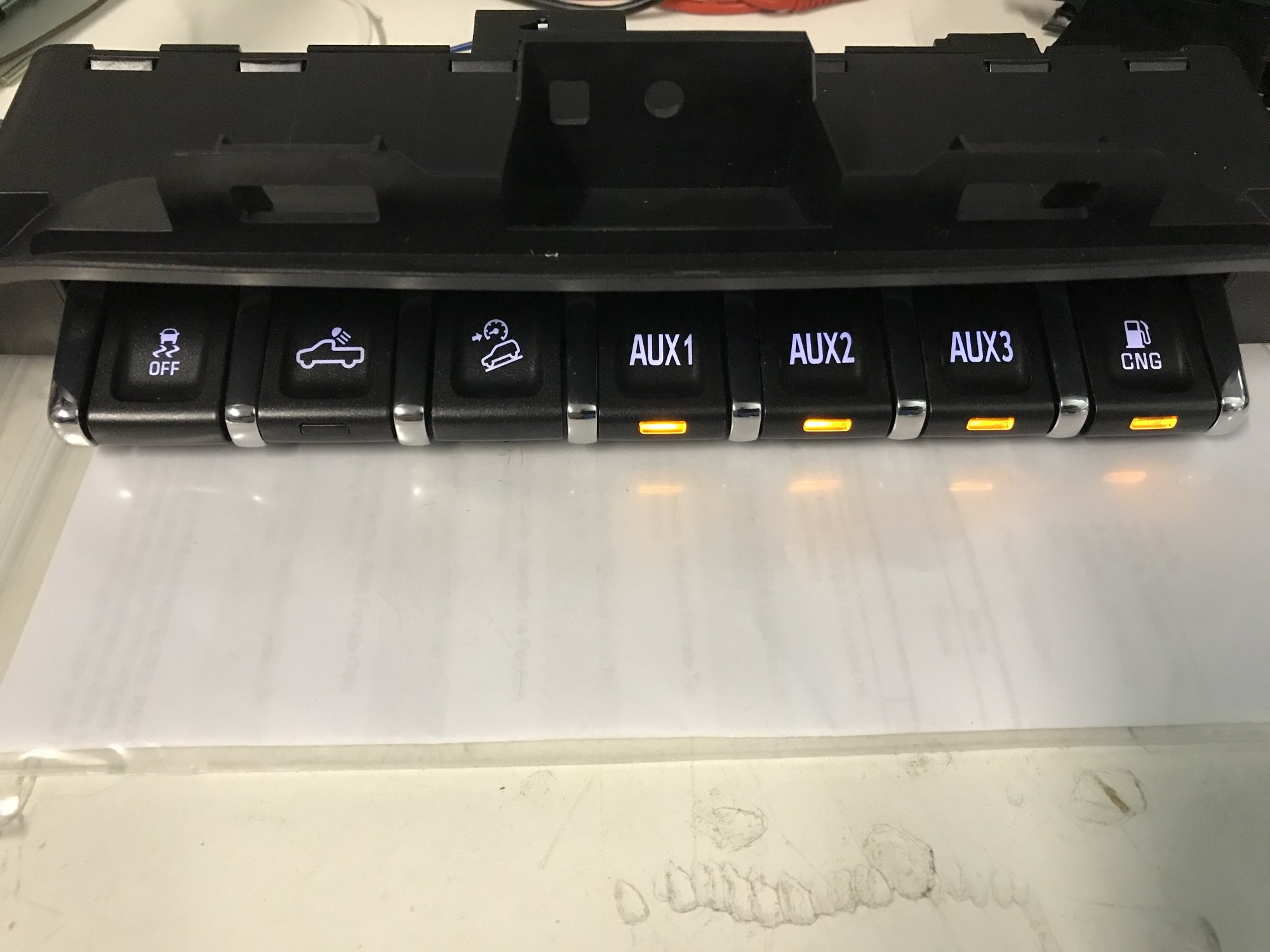
These are the only AUX switchbanks I’ve found...
-
Ok perfect, I just messed with one of those yesterday. The main plug that plugs into the back of it (18 cavities) is known as the (X1 connector) the smaller plug for exhaust brake or CNG (6 cavities) is known as the X2 connector. You likely have an unused blank slot (no pins) where the CNG or Exhaust Brake would otherwise plug in with a 6 wire harness docked there (doing nothing). As far as the AUX switches 1-4 go, their output comes through pins 10-14 in the X1 connector. Your T/C and Cargo come through cavities #17&18 of this same connector. Cavities 10-14 will likely (unless you’re really lucky) have no wires present. This is where you need to insert four wires. (One for each Aux switch). You will have to disassemble the X1 connector and release the TPA lock to insert these wires but it’s not very hard. Those four wires will have a constant negative or ground signal depending on if the switch has been pressed or not. Take that signal and apply it to pin #86 of a relay as a trigger. With pin #85 connected to a switched ignition source the relay will turn on or close or switchover whenever you apply ground (negative) to pin #86 by pressing an Aux switch button. This will cause pin #30 of the relay to connect to pin #87 and out to your accessory. Pin #30 will be your fused power supply. Now for the HDC button. The new CNG button is a momentary button meaning it only sends a signal as long as you’re pushing it. The HDC on your original switch works the same way but they don’t use the same output pin. You need to connect the wire from pin#4 in the X1 connector (HDC switch signal) to pin #4 of the X2 connector (CNG or Exhaust Brake control signal). These two connectors use a different terminal on the end of the wire so it’s not as easy as removing form X1 and adding to X2. If you have that 6 position or cavity plug sitting there in the blank X2 slot you can use this. The easy way would be to cut the wire coming out of pin#4 in the X2 connector with enough length to connect it to the wire coming from the X1 connector. Now your CNG switch’s output will be sending a signal through the wire from X1 for HDC. Don’t worry about removing the HDC wire from the X1 connector as it doesn’t connect to anything in the circuit board on your new switch. If you don’t have the 6 position plug X2 sitting there then you will need to buy a terminal and make a lead. I don’t recall the part number for the X2 terminal off hand but I’ll find it next time I’m at the bench. I hope this helps and sorry for the long winded response but I just wanted to be clear.
-
Which three buttons did your truck originally come with? I’m assuming TC, Cargo, and ?
-
I believe the relays in the new X50A are fused at 30A. You could also just add your own relays without the new Underhood fuse box (X50A) and just use something a little beefier like 70A Hella relays.
-
I just tested an Upfitter switch with a CNG button (23146445) and it seems to be identical to the one with TC,Cargo,Exhaust Brake (23145163?). The output and indicator input use the Exhaust Brake plug (X2). If you were to use this CNG switch, or the Exhaust Brake switch inyour application you would need to remove terminal/wire 4 from the X1 connector (main plug) and swap into pin 4 on the X2 connector (exhaust brake plug). The terminals are a different size so a cut and splice would be necessary or just replacing the terminal. This would allow the use or triggering of HDC through the Output pin from CNG or Exhaust Brake. You would just pop on an HDC cap in place of CNG, then move the CNG cap to say Aux 4 to use as your slip tank Trigger.
-
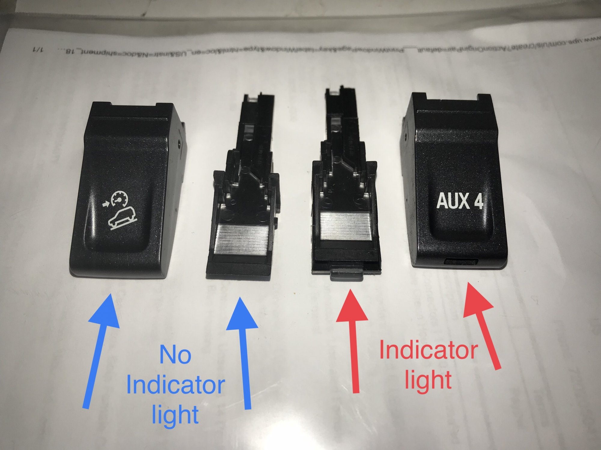
Each switch has its own pin-out in the main plug that plugs into the switch bank. The exhaust brake uses a separate plug that is a blank on a truck with a gas motor. If you have a truck with T/C, Cargo Light, and HDC and you plug in a switch with those options plus a few more, your options will still work and all switches will be illuminated with the dimmer but the extra switches will be sending a signal to an open cavity in the main plug. (No wire will be present in the plug) I haven’t had the opportunity to test a panel with CNG but I assume it sends the signal through one of the pins in the main plug. You would locate that pin on the switch and move the wire in your plug corresponding with HDC over to the cavity corresponding with the signal from CNG. On switches that have an indicator light there will be a second wire coming back to that switch as well. Upfitter switches don’t need a second wire for an indicator light as the switch will stay closed (like a clicker pen) until pressed again. Since HDC has no indicator light and CNG does you would not utilize the indicator light and have to slightly modify the inside of the toggle cap (the part that disperses the light) as it will slightly contact the indicator LED. It’s just a little trim job on thin plastic.
-
Obviously you wouldn’t have the right size HDC button cap for that switch. I’m waiting on my BCM to come back from White Auto & Media so I’m going to say hold off on the X50A until I can test the one that I just got in my “15 6.0 just to be sure it’s compatible. I do have a couple extra HDC button caps and I’ll gladly mail one to you so you can use the CNG one for your slip tank in place of say AUX 4. I’ll get part numbers for terminals together soon to save money over buying terminated leads through GM.
-
Yes, that switch would work but the Exhaust Brake uses the other connector on the back. You likely have some wires plugged into a “blank” on the back of your switch now. The exhaust brake has 6 pins at that plug, two of which are used for our purposes. The exhaust brake plug and the main plug use different terminals. You could easily cut and splice but this switch might be better suited as you can just relocate The HDC terminal to the cavity on the main switch plug that corresponds with the CNG pinout. Unfortunately I don’t have a diagram for that but it’s easy to find which one that is using a multimeter. (Assuming it doesn’t use the same plug as the exhaust brake). I have only seen this switch on eBay but it’s around $30 US.
-
Hi there, I’ve been working on a comprehensive video on all of this with part numbers and explanations, diagrams etc. you have a few options that are pretty easy since you don’t have adjustable pedals. I just got my new X50A (under hood fuse box) in the mail and found a new relay for a second fuel pump. The reason I bought it was for the four AUX/Upfitter relays. This would be perfect for your application. If you can hang in there a few more weeks I’ll have everything complete and post the video.
-
Seat Memory Integration (RPO - A45) by pgamboa
TinkeringFox replied to pgamboa's topic in Modifications & Accessories
Phil, you’re the man! That’s incredible! Great job ??- 47 replies
-
- 1
-

-
- seat memory
- seat memory upgrade
- (and 5 more)
-
What have you done to your K2 today?
TinkeringFox replied to block8head's topic in Modifications & Accessories
Ho Lee Fook.........Octopus. -
What have you done to your K2 today?
TinkeringFox replied to block8head's topic in Modifications & Accessories
Very cool ?! Were you able to decipher the wiring in that donor dash? -
Heated steering wheel
TinkeringFox replied to Dennisfiremanny's topic in 2014-2018 Silverado 1500 & Sierra 1500
It may be the difference between a 1/2 ton and an HD.


-
Forum Statistics
250.4k
Total Topics2.7m
Total Posts -
Member Statistics
342,759
Total Members8,960
Most Online
-
Who's Online 8 Members, 1 Anonymous, 1,170 Guests (See full list)