

Vuk
-
Posts
62 -
Joined
-
Last visited
Content Type
Profiles
Forums
Gallery
Events
Articles
RPO
Store
Blogs
Everything posted by Vuk
-
As far as I understand, if you don't have AUX switches out of the factory, you can't get away without playing around with wiring. You might find it easier to use the HomeLink buttons on the ceiling - someone posted about a kit for those a long time ago so that link is broken; not sure if those kits are still out there.
-
I am in the process of doing that exact same thing and I want those accessories available always (regardless of the key position), and supplied from the AUX battery. First of all you need to "criss-cross" two switch blocks like myself above. Additionally, since LDW and Exhaust Brake switches (or, your new AUX1/AUX2) are pushbuttons, both of us will need to add latching relays to be able to toggle accessories from those switches. I have modified the switch block as above to be able to have the indicators light up regardless of the key position, and will soon wrap this up with two latching relay circuits. I have been working on other things so couldn't finish this, but will follow up on my previous post when I am done.
-
The Run/Crank Ignition signal can be found right there in the X51L left instrument panel fuse block, and I think that would be enough to fix the remote start problem. So, according to the updated schematic, the sensor power supply will be cut off if either the accessories are on, or the engine is cranking/running. Scenario 1: You unlock the truck, sit in the seat and the moment you turn the key, audio sensor is disabled and you won't get hood open warnings (because RAP signal disables the sensor) Scenario 2: You perform remote start and as soon as cranking is initiated, audio sensor is disabled and there is no chance of an open hood condition during remote cranking/running (because RUN/CRANK signal disables the sensor) I will try to wire this today/tomorrow and this should wrap up this specific mod (I still haven't had time to wire up the remaining of the sensors though...).
-
I edited the schematic in the first post to include components required to "emulate" the hood switch operation - diode+resistor in parallel to hood switch. This is neccessary because the hood switch does not simply ground out the signal wire when the hood is opened, but rather changes resistance. I think I have a simple fix for the remote start issue which I will soon test and post my findings; otherwise the sensor has been working predictably for the past week.
-
Violet/brown; check my post on previous page, that's where it goes factory but many other signals will work. What's the make/model of that isolator?
-
I did not wire into the cab - just tapped into the engine/body harness connector (the big one right there next to the aux battery).
-
That looks great but I am not sure if that device exposes an output that can be used without one of the compatible main units - that is can it be used to directly drive relays?
-
I just discovered one problem with this approach. When the engine is started with remote start, the accessory power is not turned on until the ignition switch is turned. Therefore, since the glass break sensor remains active, the engine will shut down the first time the "open hood" state is detected (which is likely due to the noise of the keys rattling). The core of this challenge is obtaining the "armed" signal - I am willing to live with the above problem for now since I have other higher priority mods on the list, but my next take on this would be to try to generate a signal that resembles the "armed" state more closely than inverted RAP. Right now, I will continue adding a shock/vibration sensor, a tilt sensor, and magnetic switches on the tailgate and the bed cap glass, as well as a glass break sensor in the bed.
-
I am trying to stick with the OEM alarm/fob system just because I don't want too many new things in there, but to add a few cheap sensors myself clearly is easy enough. I wonder if it's hard to add the OEM tilt sensor? It might just be easier to use the hood switch as a hook for an aftermarket tilt sensor.
-
OK, so the general wiring is laid out and I couldn't finish it today because of that wire grommet on the firewall... Spent too much time on that with no success. Back to the audio sensor, it seems to be working well, and just a couple repetitive knocks on the windows with any metal tool are all it takes to set it off. Note that this specific sensor will not detect punches against the windows or body panels. Within a couple of days I will update the schematic with the diode-resistor that are needed to emulate the hood switch.
-
Update from today: The left side of the schematic is working properly - I can see that the sensor is powered only after the key is taken out and the driver opens the door (i.e., RAP goes off). On the right side I have not been successful in finding the hood switch wires in the X115 engine/body harness connector. It should be super easy to tap directly into the hood switch, but it got dark and a little cold to work outside so I called it a day. I will report back when that part is done and the testing stage comes up. Edit: I did just realized that I missed something: the hood switch is not just a plain switch but adds a specific resistance between the wires (different when open/closed). So, it won't just be "shorting the wires with a relay", but a bit more than that - I will make sure I post an updated schematic once all is figured out.
-
I am trying to integrate an aftermarket audio sensor into the factory alarm system on my 2016 Sierra 1500 AllTerrain, so I thought I would share my thoughts. I picked up a DEI (Directed Electronics) 506T audio sensor which seems to be working well. It detects key rattling almost instantly, and also responds to repetitive knocks on glass with metal (i.e., key, screwdriver). It's interface is simple: three wires; +12V, ground, signal output. Problem 1. Looking after a place to integrate additional sensors I found that the simplest thing to do would be to emulate opening of the hood. The wiring for the hood switch is easily accessible, and the OEM alarm system reacts to the hood switch instantly when armed. Essentially, I would like to use the output of the audio sensor to drive a relay that will close the hood switch making knocking on the glass equivalent to opening the hood. The sensor appears to consume very little (<1mA), so there's no problem in having it run all the time. However, I wouldn't like the DIC to keep displaying the open hood warning under normal conditions since the sensor triggers easily on human voice and many other sounds. Problem 2. I've looked around the builder's manual and couldn't find any wire that carries an "alarm armed" signal. Therefore, the best I could think of doing is creating an inverted RAP signal - when retained power accessories go off, the audio sensor powers on. Yes, this may mean that the hood will be sensed as open by the OEM alarm in the time between taking the key out and arming the system (i.e., by locking the truck). I don't think this will be a problem because the OEM alarm will wait for all doors to shut in order to arm the system. I might be missing some condition under which this could be a problem? Going towards executing this, I prepared everything and the weather has been slowing me down. Basically, I will add one relay that will be able to close the hood switch, and another one that will cut the power to the sensor when RAP is enabled (or conversely, supply the power to the sensor when RAP shuts off). I am looking forward to completing some tests and reporting back results. I also plan to add two magnetic switches to the sensor (one for the tailgate and one for the bed cap rear glass), as well as another audio sensor in the bed of the truck (for my cap), but putting sensors in parallel is a breeze if this ends up working. Notes: There are a plethora of wires one can tap into to achieve this, and for my specific truck configuration I think signals in the schematic below will work. Also, you could probably get away with just shorting the hood open switch signal to ground (instead of the low reference), but I just wanted to minimize any possible effect on the OEM system. Additionally, the mentioned sensor drives a low level on the signal output, which I have ignored in the schematic - this can be converted to a high level to drive a relay with a simple transistor circuit or perhaps with another relay. Maybe even the audio sensor driving low level on the output could be connected directly to the hood open switch signal without any additional components, but like I said, I just wanted to minimize any possible effects on the OEM system.

-
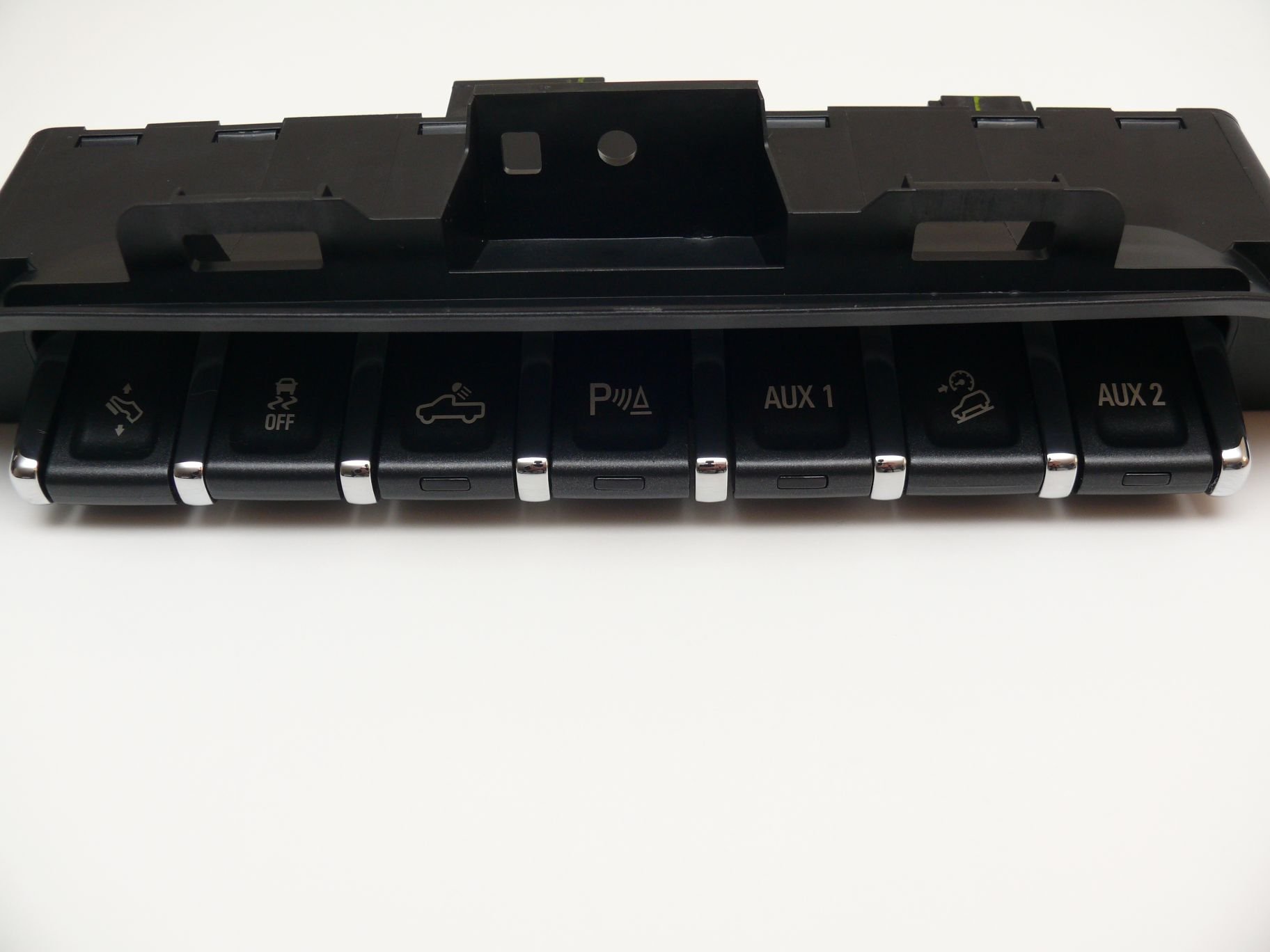
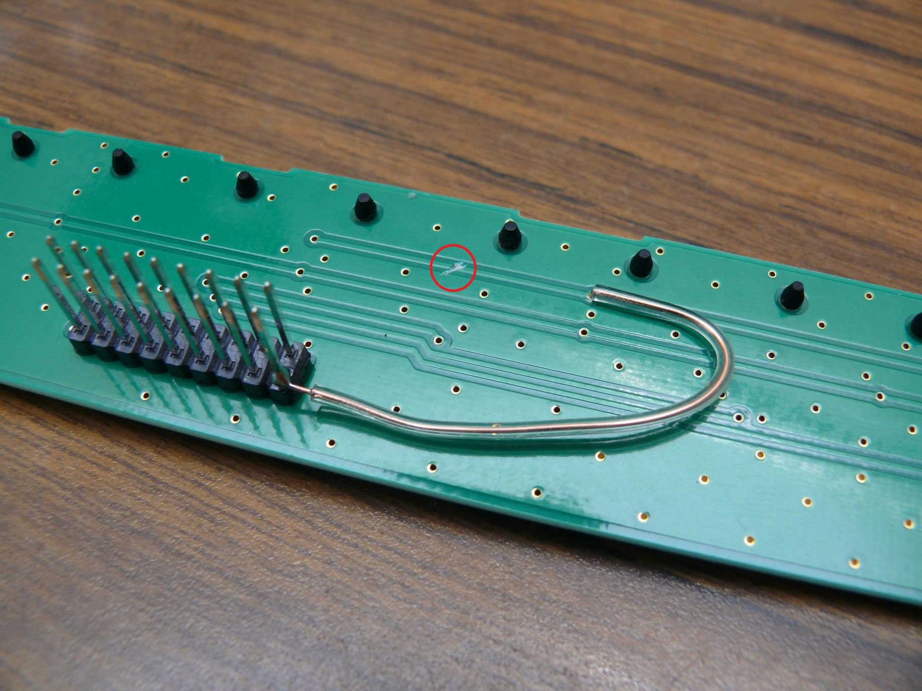
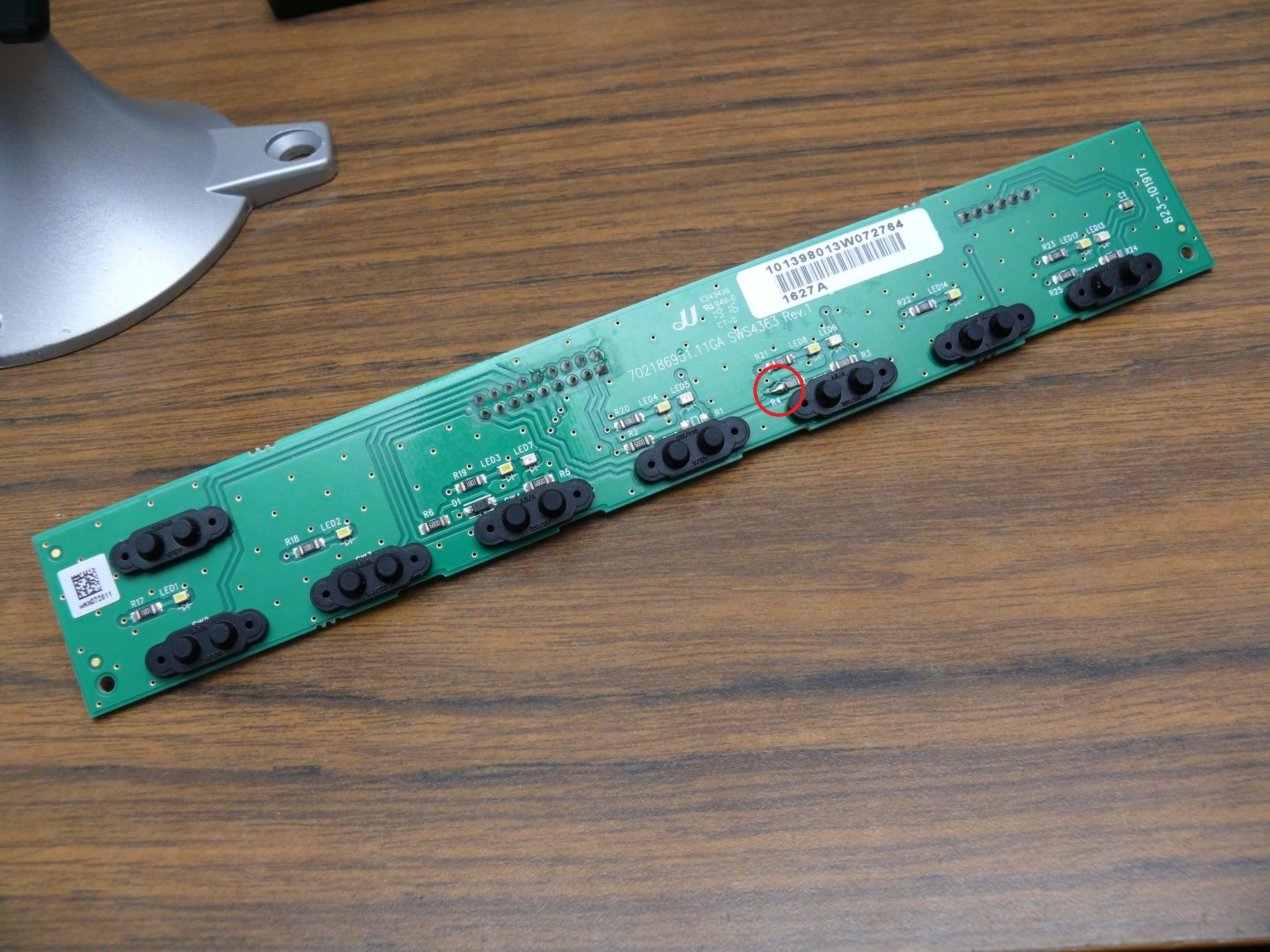
OK, so the answer to this questions is Yes, the pinout of the switchboard should be the same. I modified the switches to separate the LED signals for AUX 1/2 (those are LDW and Exhaust Brake) because I want those accessories powered from the auxiliary battery and available all the time - hence I want the signals to show if they are on regardless of the lighting of the rest of the dashboard. The next step for me is to see if I can use any of the wiring on the truck or need to run everything for these two switches again. Note again that you only need to do this if you want the AUX 1/2 indicators to have a power supply separate from the rest of the instrument cluster. Note: Yes, these are momentary circuits so I will add a latching relay circuit per switch and post about the remaining of the process.
-
Inverters with two sets of 12V screw terminals appear to be common in the range above 2000W. I suppose that if say one fused link fails, the other fuse would blow quickly as, like you said, it cannot handle that load all alone.
-
The installation manual for the inverter says to run two 00 gauge lines that are fused with 250Amp fuses each. I think that if you keep the length of the two wires close to identical, there should be no issues.
-
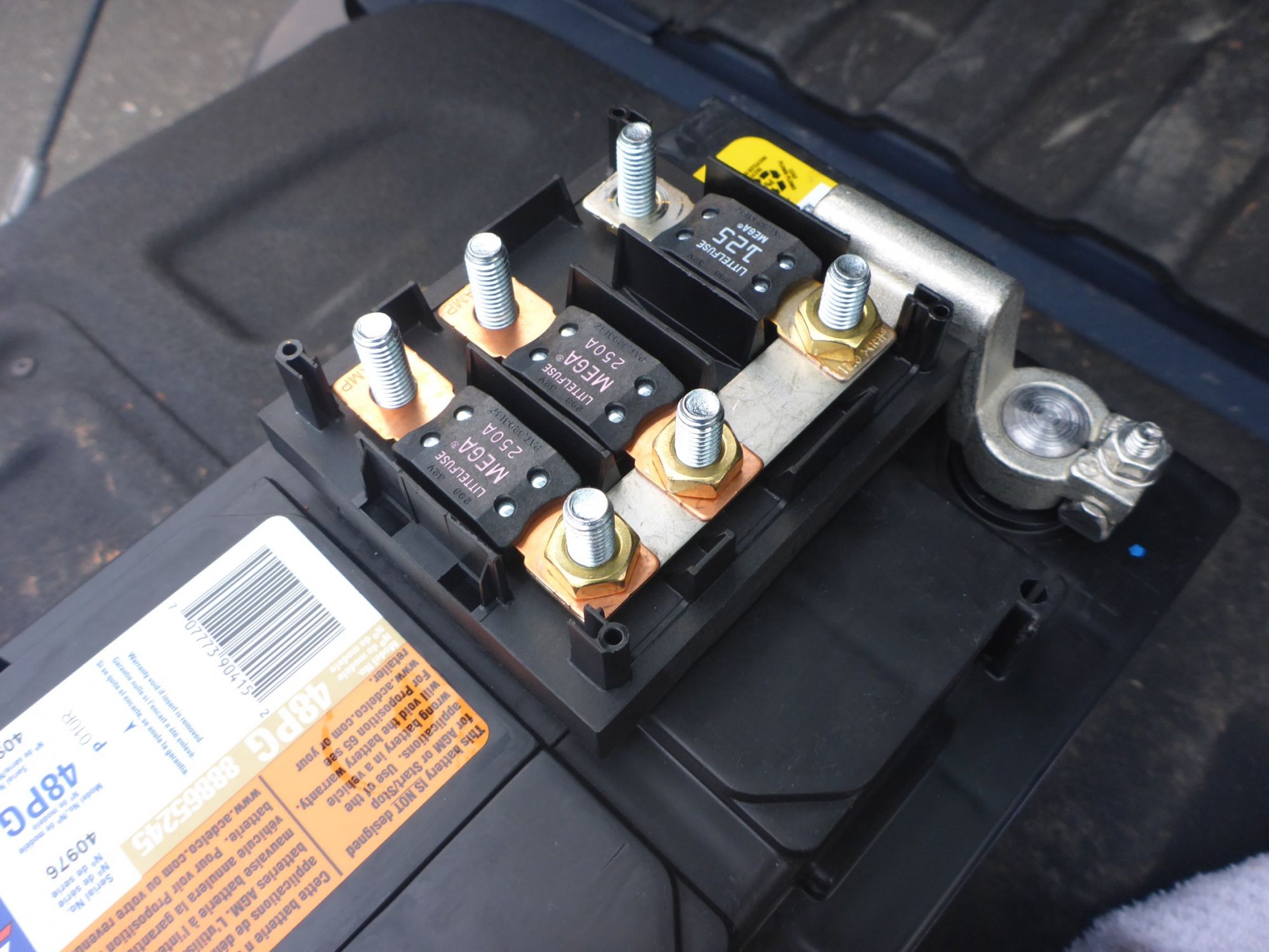
My setup is complete now with nice factory-looking points to hook up an inverter. Should I ever need to jump start the primary battery, I can always run jump cables from aux battery to the primary.
-
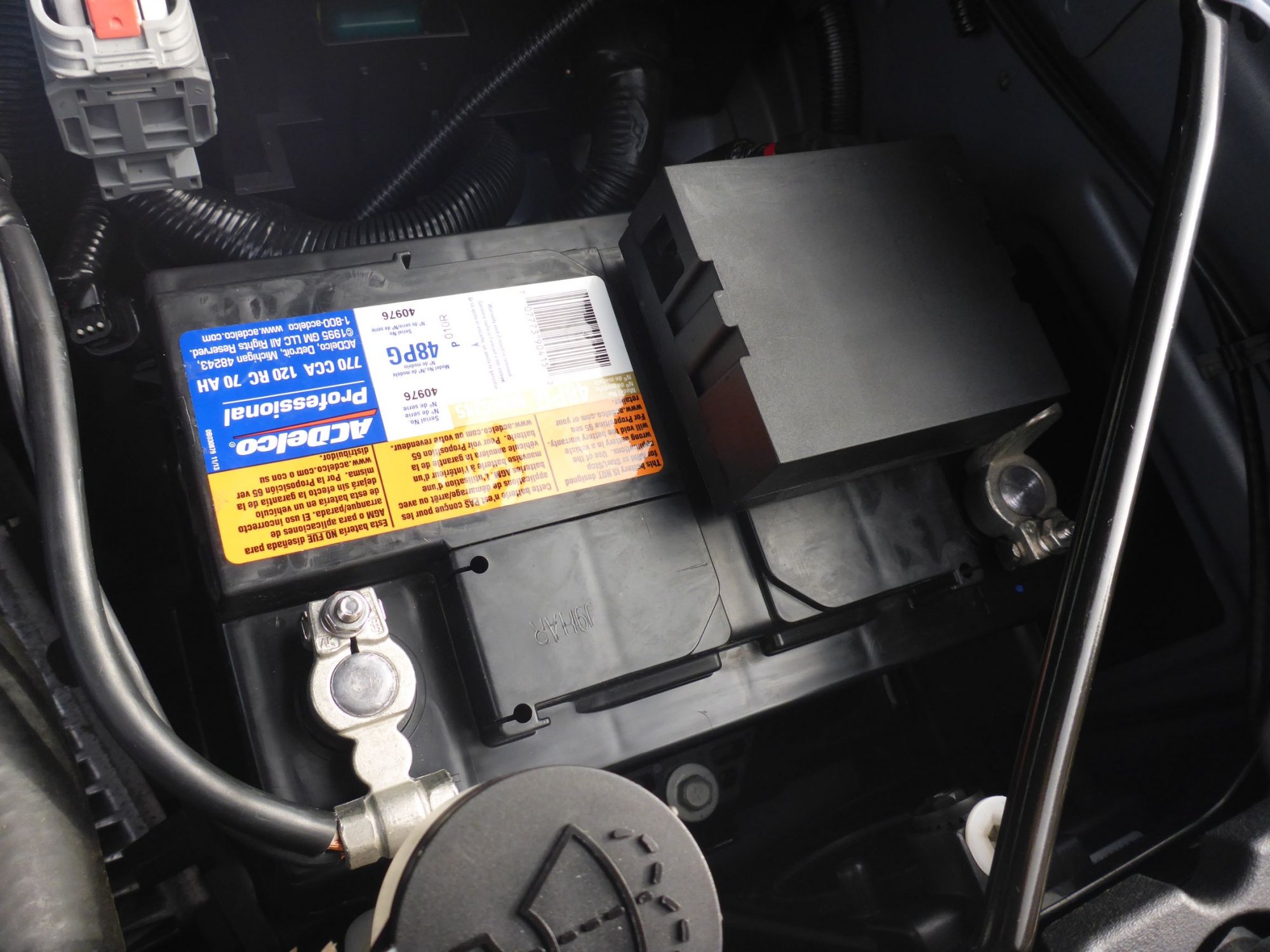
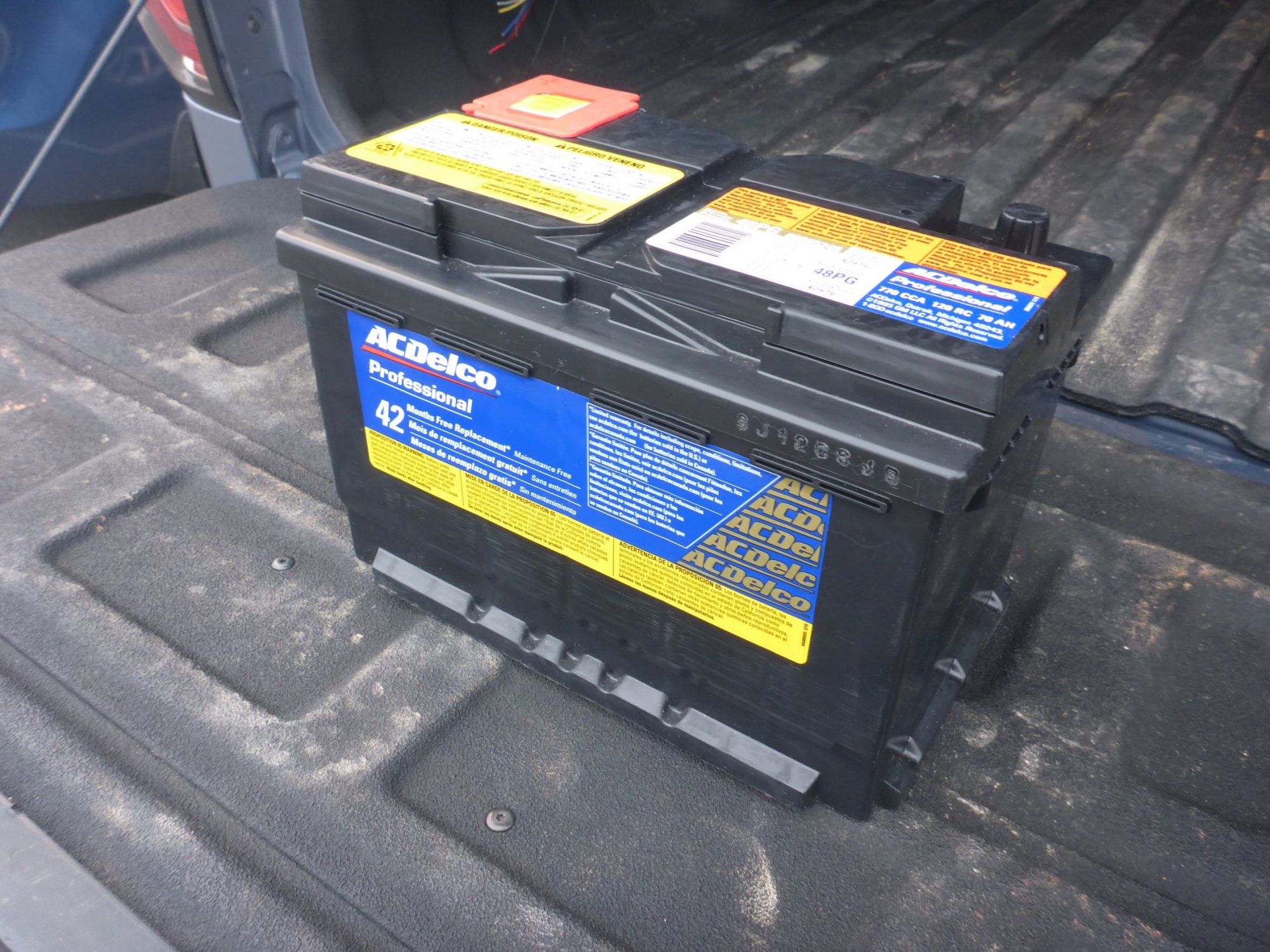
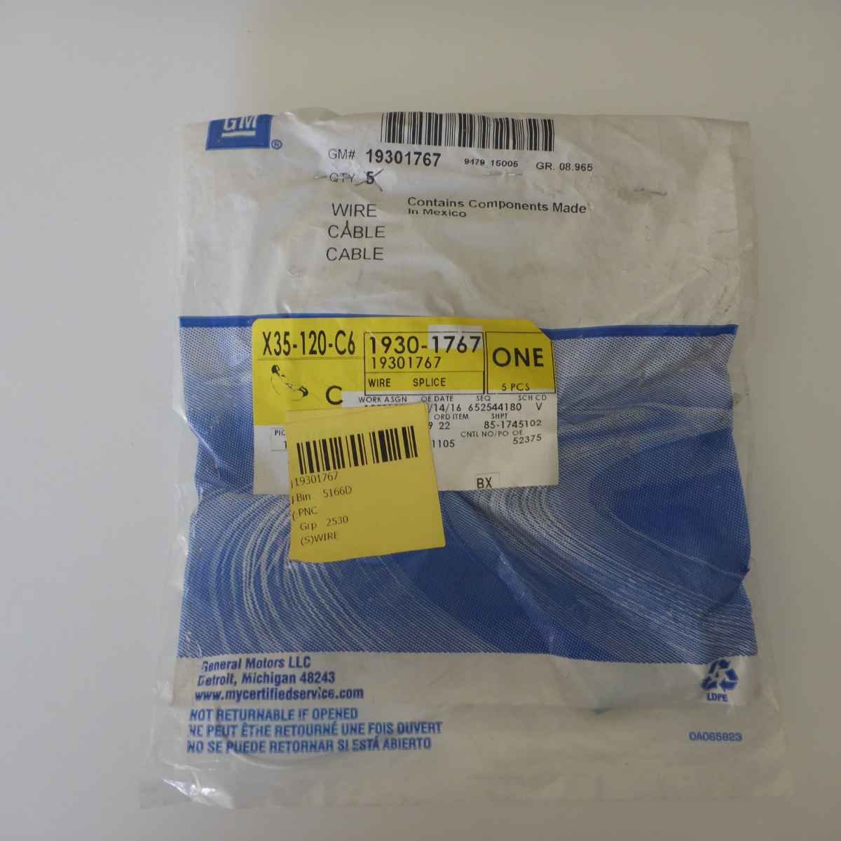
I picked up a 48PG battery today and installed my three-fuse modification. The original negative auxiliary battery cable 84354708 seems like it would never be delivered, so I picked up 22846471 (at about the same price) and removed the sensor. This one gives an additional ground lead of decent gauge that can be used for accessories, which is even better. I've replaced the 175A fuses with 250A as a preparation for a 3000W inverter running off of the aux battery. I will post pics once the battery lays down in the next couple of days.
-
I've decided to kiss this frame goodbye in about 5 years and build a galvanized one to support V8 tuning (if the motor and cab stay well by then). Anyway, not sure how the previous owner treated the undercarriage given salty NJ roads, but just looking at condition of very old vehicles that have not been specially treated is disappointing (and appears to be by no means exclusive to GM trucks).
-
I recently finished repairing some of the rust in the rear end (under the bed) on my 2016 Sierra 1500 AllTerrain (came from NJ, has 40k miles now). Sincerely, it is disappointing that these trucks rust so badly so quickly. 30-year old cars have undercarriages in better shape. Regardless, I think the wax GM is using is indeed a good product, the only problem being thin application. When cleaning it off to prepare for painting, the spots where there were tears (i.e., thick application) it was very resistant to getting off of the frame, and the metal underneath was intact. On the other hand, spots where the layer was very thin is where it washed off quickly, and water and contaminants started penetrating from there on - hence the peeling.
-
Could be that it has changed at some point during 2018; I am not knowledgeable enough to say anything about that.
-
All the wiring info is from the 2018 builder's manual. The part numbers I got printed out from a dealer, so not sure if the battery tray or the harness would be the same.
-
My truck has the switch block 23145162 (Pedals / TC / Dome Light / Park Assist / HDC). Does this mean that if I buy 23145202 (Pedals / TC / Cargo Light / Park Assist / LDW / HDC / Exhaust Brake), everything will continue working but I will be able to use the LDW and Exhaust Brake switches for accessories? I am OK with hardwiring into the switch block. Thank you!
-
In fact, ECUs can estimate the battery capacity by keeping track of the discharge rate through the current sensor, which these trucks have. I wanted an auxiliary battery for a 2-3kW inverter, but thought that it would also provide me with a secure start in case my primary battery dies (just of old age because the BCM seems to reserve the right to shut things off if the battery discharges below a certain point). The fact that the factory fuse between the batteries is 125A explains that the aux battery is not meant for cranking.
-
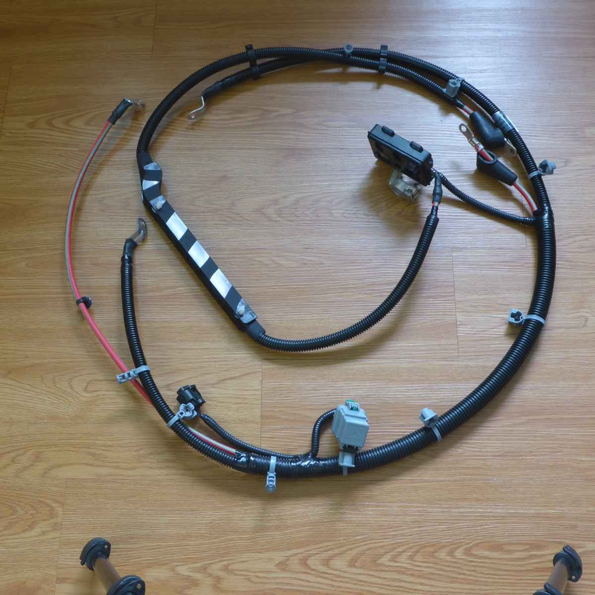
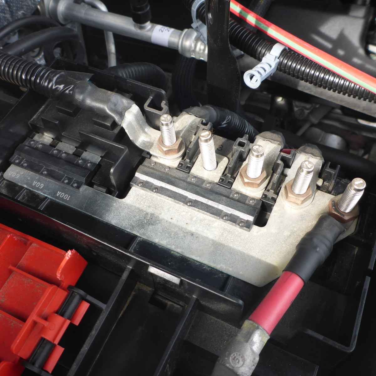
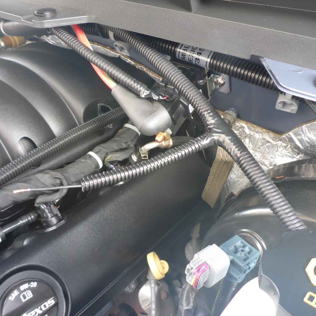
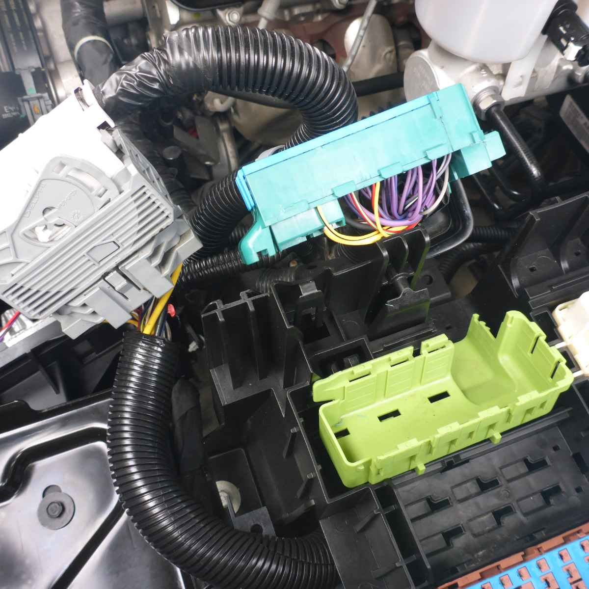
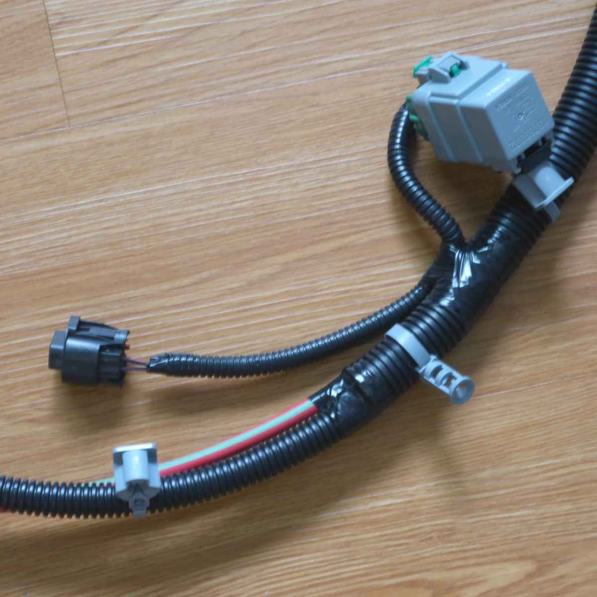
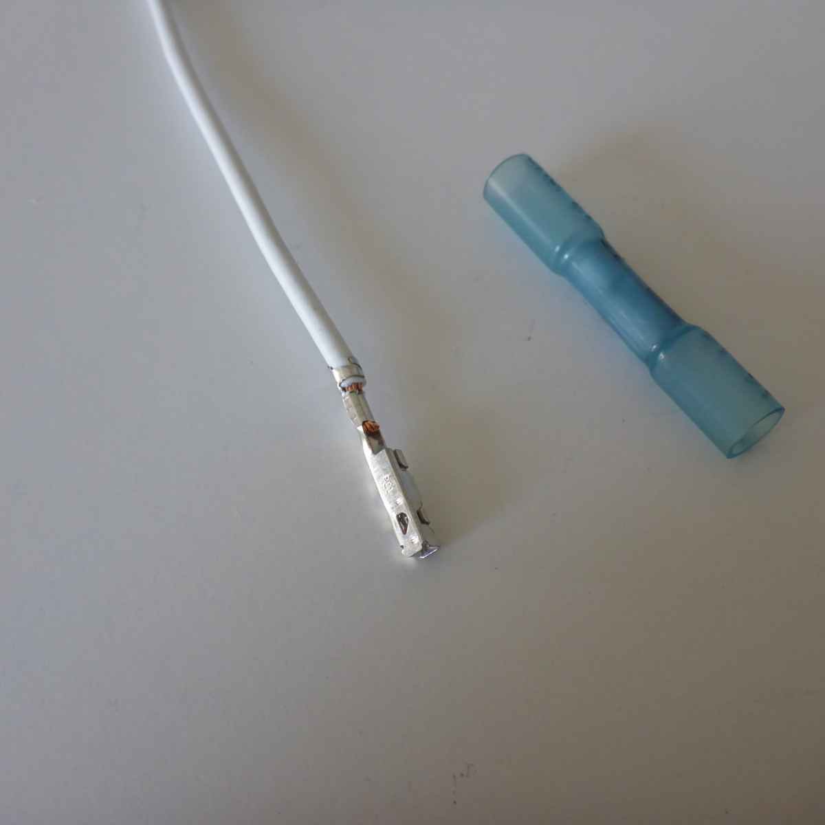
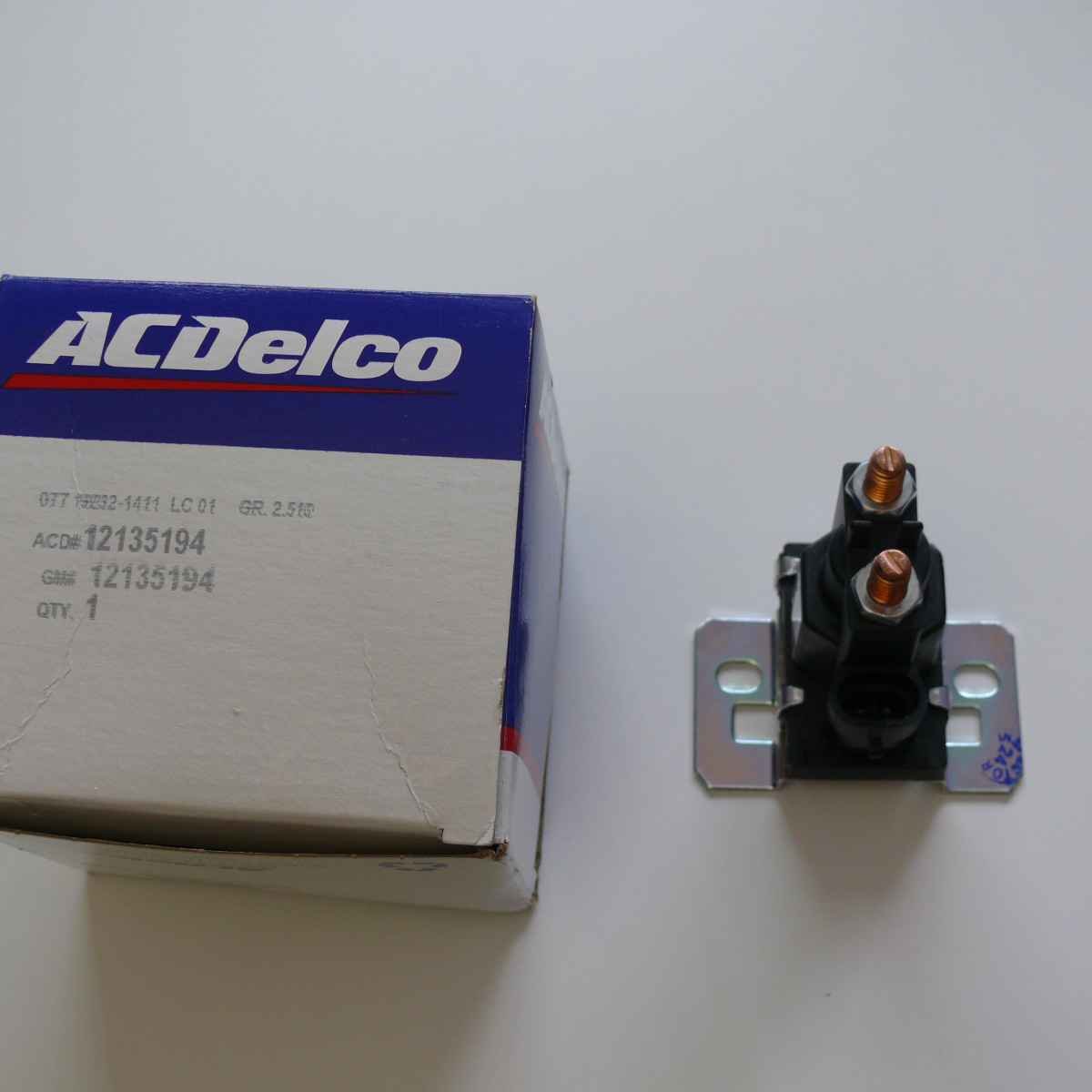
This is the battery tray, secondary auxiliary relay, and the optional 3 fuse box and cover for older model years if you want to replace the single fuse box on the aux battery harness: This is the factory harness between the primary battery and the X50A underhood fuse box: This is the aux battery harness that replaces it and adds the relay for switching the battery isolator, cable running from the primary battery distribution block to the isolator, cable running from the isolator to the aux battery (including the battery terminal with a 125A fuse), the connector for controlling the isolator, and the connector to control the aux battery switching: Here you can see the blank screw on the primary battery distribution block - the cable running to the isolator hooks up there. This is the connector on the aux battery harness where ground, (+), and the control signal (run/ignition) need to get in: This is the service terminals that connects to that connector. I ran black, violet/brown, red/white wires in the standard flex installation hose along the firewall (connector is on passenger side, my wiring goes back to the driver side) Here is the battery isolator secured to the firewall. I pulled out the black wire right there to connect to the ground post. This is the connector where you need to connect the red/white wire from the harness (the terminated lead wire is white) This shows where things come together with the red/white wire going to the service connector: Violet/brown can just be tapped into on the engine/body connector: All done (except for the aux battery which is on order, so I left the cable going to it disconnected from the isolator just to avoid having to heavily isolate it).
-
Yes, I will post detailed pics in a couple of days - I am fighting the frame rust for the past couple of days...


-
Forum Statistics
250.3k
Total Topics2.7m
Total Posts -
Member Statistics
342,720
Total Members8,960
Most Online
-
Who's Online 0 Members, 0 Anonymous, 611 Guests (See full list)
- There are no registered users currently online