

Vuk
-
Posts
62 -
Joined
-
Last visited
1 Follower
Vuk's Achievements
")
Enthusiast (3/11)
38
Reputation
-

L83 (1500 with current sensor) biggest OEM alternator
Vuk replied to Vuk's topic in Modifications & Accessories
There seems to be a new offering of aftermarket 250/320/400Amp alternators for this generation of trucks from Mechman: https://www.mechman.com/alternators/gmc/sierra/5-3l/2014-2018/ Also, there seem to be 250/320/370/400Amp versions from JS Alternators that are to be used with the factory ECU-controlled voltage: https://js-alternators.com/products/2005-2019-gmc-sierra-1500-5-3l-250-320-370-400amp-high-output-alternator Has anyone had experience with these? -
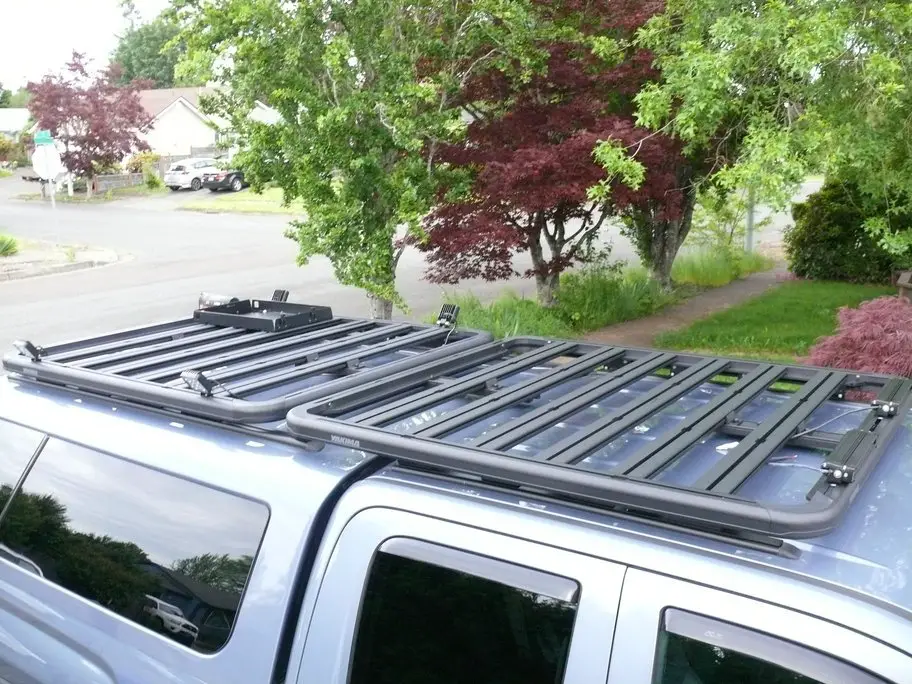
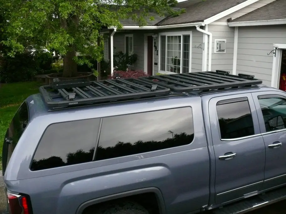
This is the latest thread on this topic I could find and wanted to share my setup that I recently completed. I have an ARE Z Series shell that had the original optional tracks. Since I very much dislike how distant the platforms are from the roof in typical applications using standard mounting brackets and hardware, I decided to custom make the platform mounts. I got a Yakima LockNLoad 55"x49" platform and used 6061 aluminum angles to secure the platform to the tracks. This part was more or less easy, and the setup is very solid. The front was much more challenging since (1) there are no tracks nor factory options for tracks, and (2) the roofline is not straight neither length-wise nor sideways. As a first step, I mounted Thule universal tracks with rivet nuts. I've had such a setup on another car for years and I believe that leaks are not an issue when installation is performed properly. I used construction-grade polyurethane sealant around the rivet nuts during installation. Then, I measured the angle of the tracks and found that I needed an angle of 84 degrees (tightening the setup with 90 degree angles would have caused something to crack, for sure later if not earlier). I had a local machine shop bend about 32" of 5052 1/8" aluminum to exactly 84 degrees (6061 is not good for bending). I cut the piece into 8 pieces and after a lot of adjustments, got the front platform to sit flush with the rear. It was very much non-trivial for a single person to handle (the Yakima platform is quite heavy), but I am very happy with the results. I want to emphasize that I intentionally positioned the platforms close to the roof because of (in my opinion) enhanced aesthetics. This particular Yakima platform does not bend at all with me standing on the roof (~180lbs). I also have a RhinoRack ladder that easily hooks up on the platform for easy loading/unloading.

-
I just went through all of my photos and can't find a photo of the actual physical wires, however, the hood switch has only two wires so if you get a diode and a resistor as shown in my schematic, there's really no bad way to wire it as long as you find the ground out of those two.
-
Are you able to see the sketched schematic in my first post? That is the one that is still working on my truck for more than two years without issues, just a resistor and diode in parallel to the hood switch. All I have is an occasional false positive from the bed sound switch when it's very windy (even though I have the hard top, the bed is of course not insulated from the environment).
-
Is it possible to revert from LED to non-LED tails? My original LED tails are full of water and they are just very much overpriced to replace. If I can revert to the non-LED option, I can put some tails worth giving so much money for (e.g., Morimoto XB). Thank you!
-
Aftermarket head unit. Post your pics.
Vuk replied to smcgillis10's topic in Modifications & Accessories
I've kept the original components in order to get the truck's cab microphone and steering wheel commands without alterations. I've drawn the original touchscreen cables into the locked glovebox in case I need to make any adjustments to vehicle settings (which I normally never touch), but I can connect the original touchscreen there quickly. You don't really lose the FM radio (except for tuning), because you can always say "tune to 95.5 FM" (I honestly only use FM for drive-in theaters and voice command for this works great). -
Aftermarket head unit. Post your pics.
Vuk replied to smcgillis10's topic in Modifications & Accessories
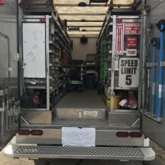
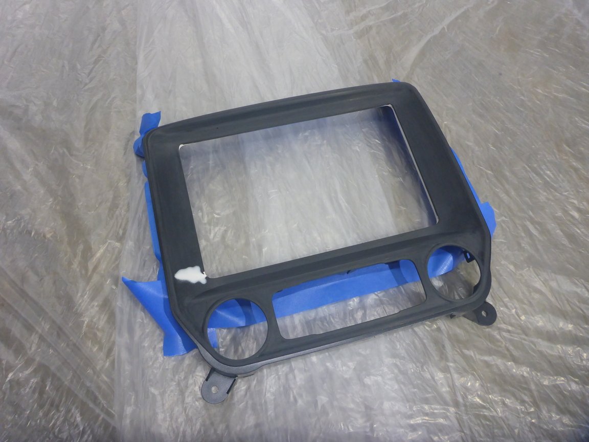
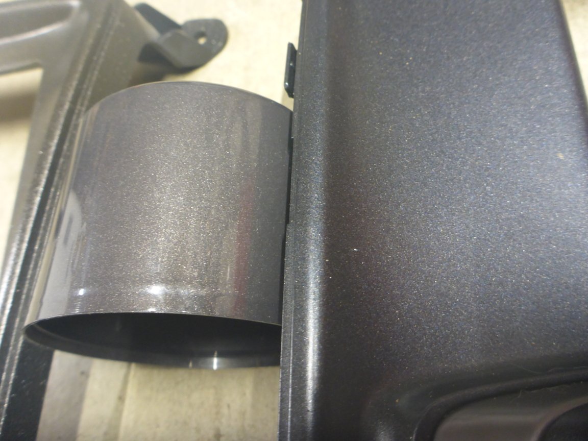
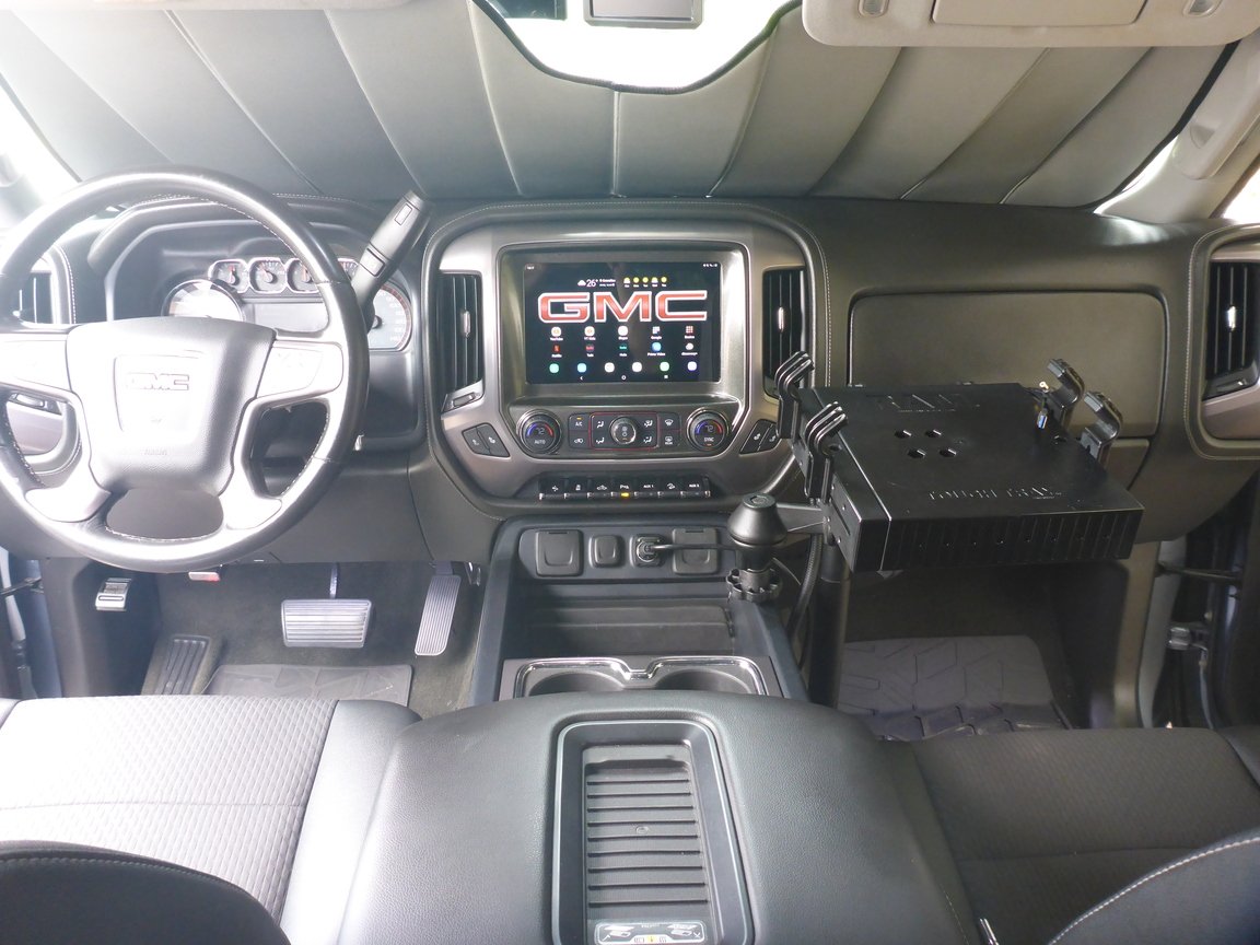
A little refresh of the topic for people who are interested; I just finished my setup. My original touchscreen started acting up - the bottom ~1" would sometimes be unresponsive to touch and I was getting frustrated by the lack of AndroidAuto features. My setup summarized: Ordered a double-DIN radio bezel Had it cut on the waterjet for a larger screen Filled up the side gaps due to bezel curvature with plastic weld putty Sanded and repainted the bezel; paint I used turned out to be a little different from the cap but nevertheless I am OK with how it looks at the end Used double-sided tape to secure an Android tablet in place and added a bracket for additional back support Wired a USB charger from one of the circuits active with ignition Sunk the CD player deeper to create space for the tablet Tablet I used is a Samsung GalaxyTab A7 10.4" 2020 model with LTE Summary of how I set everything up Tablet is on all the time, this circumvents the need to wait for bootup and also allows vehicle tracking via location sharing When the key is turned, charging begins, tablet must be unlocked only once, and will remain unlocked while vehicle in use (Smart Lock feature) The screen will stay on while vehicle is in use, that is, while charging works (Android option) The tablet connects via Bluetooth so all steering wheel commands are operational When the key is removed and the door is opened, major music apps stop, and since there's nothing keeping the system from locking, it locks after 15 seconds If tablet ever gets fully discharged and it needs a hard power-on (via power button), or there is a major I can access the button through a tiny hole with a SIM card ejection tool and press the button Some pictures:
-
That battery post is the original on 23273450 GM dual battery harness, with the exception that it connects to a single fuse holder. The height and angles work for this fuse box, too.
-
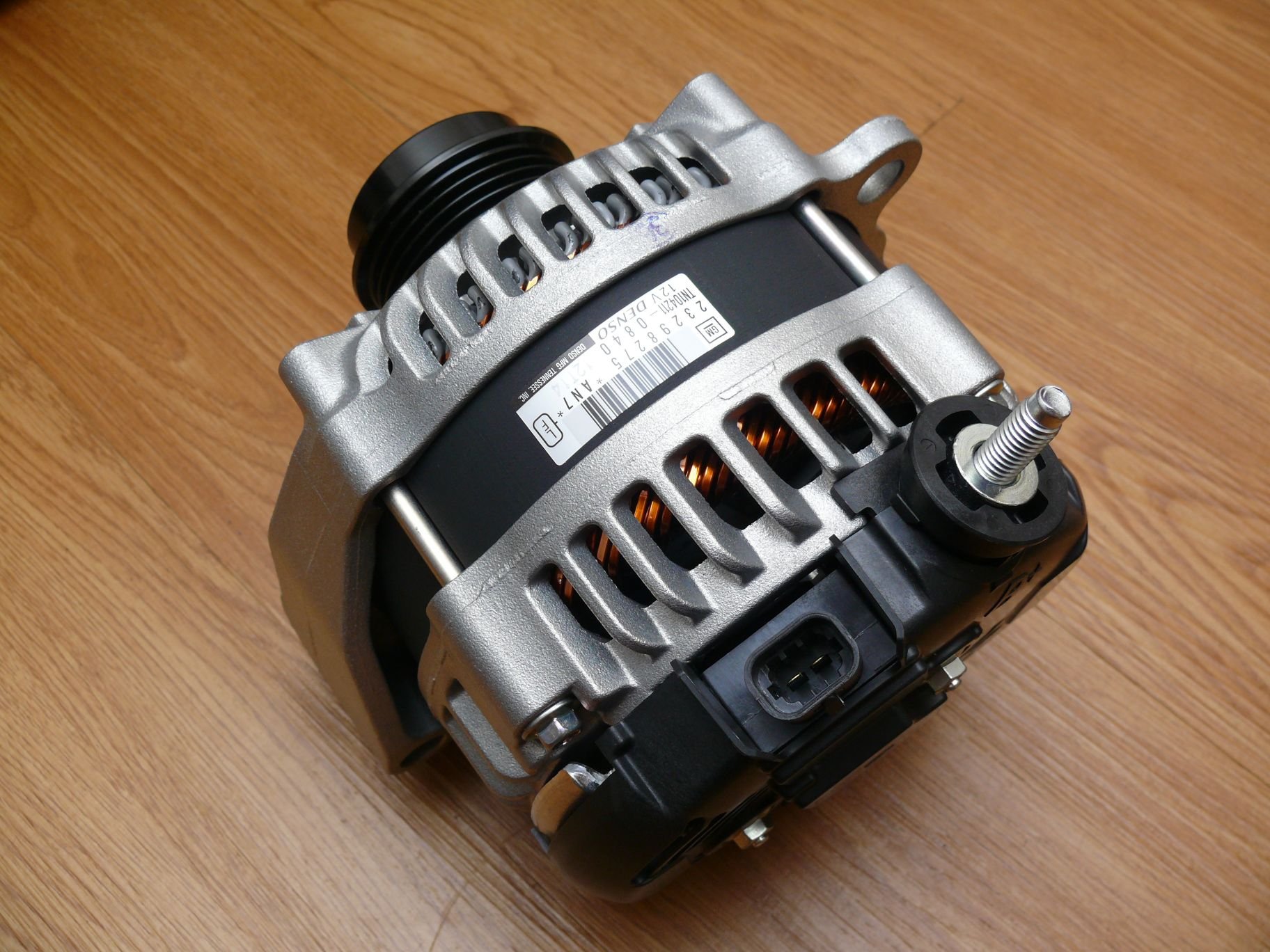
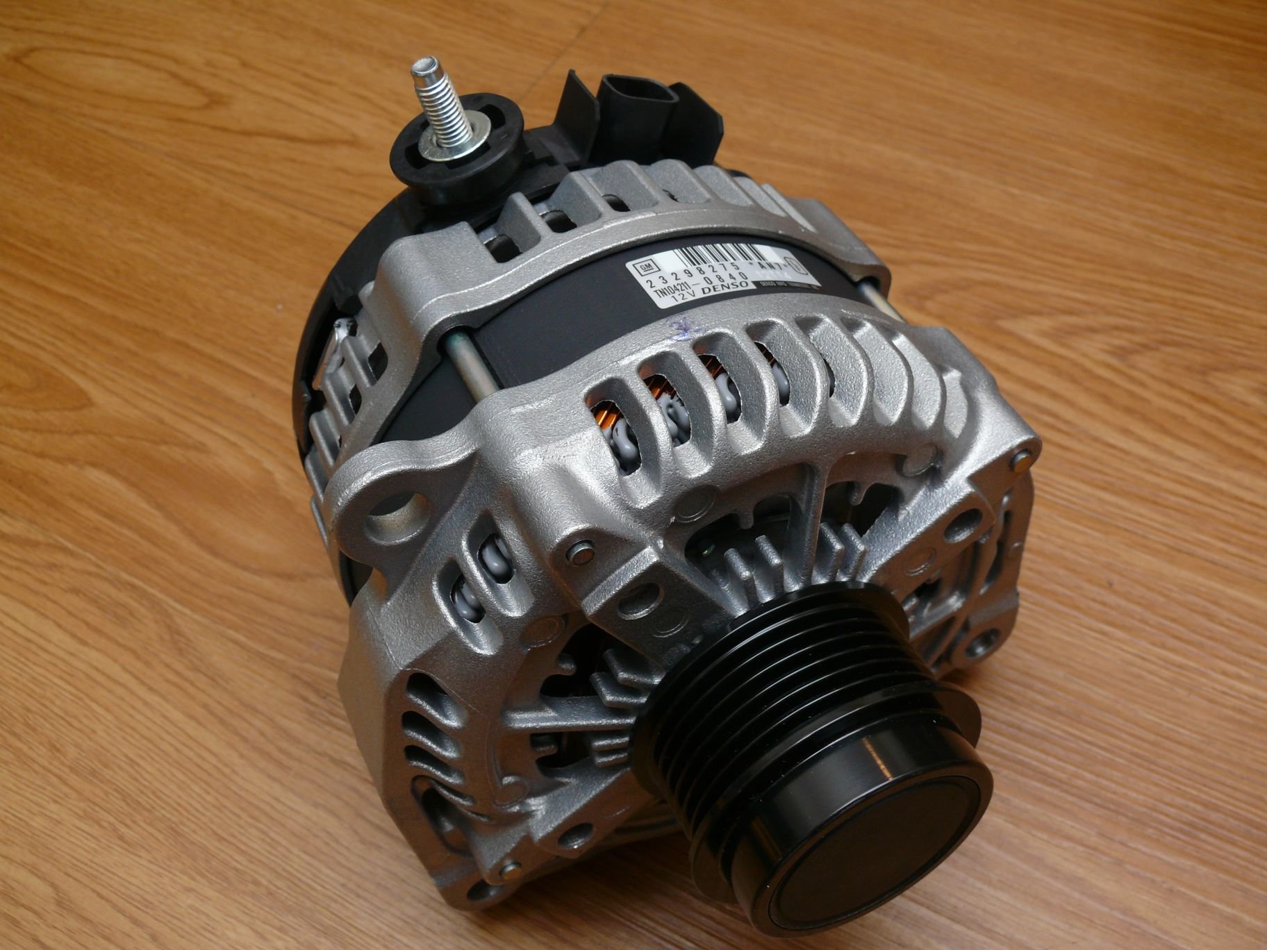
L83 (1500 with current sensor) biggest OEM alternator
Vuk replied to Vuk's topic in Modifications & Accessories
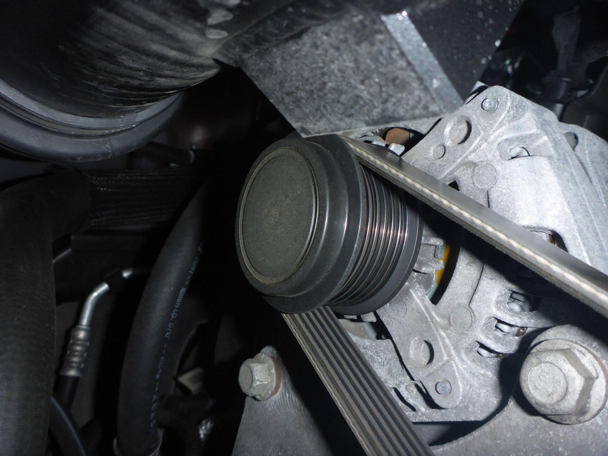
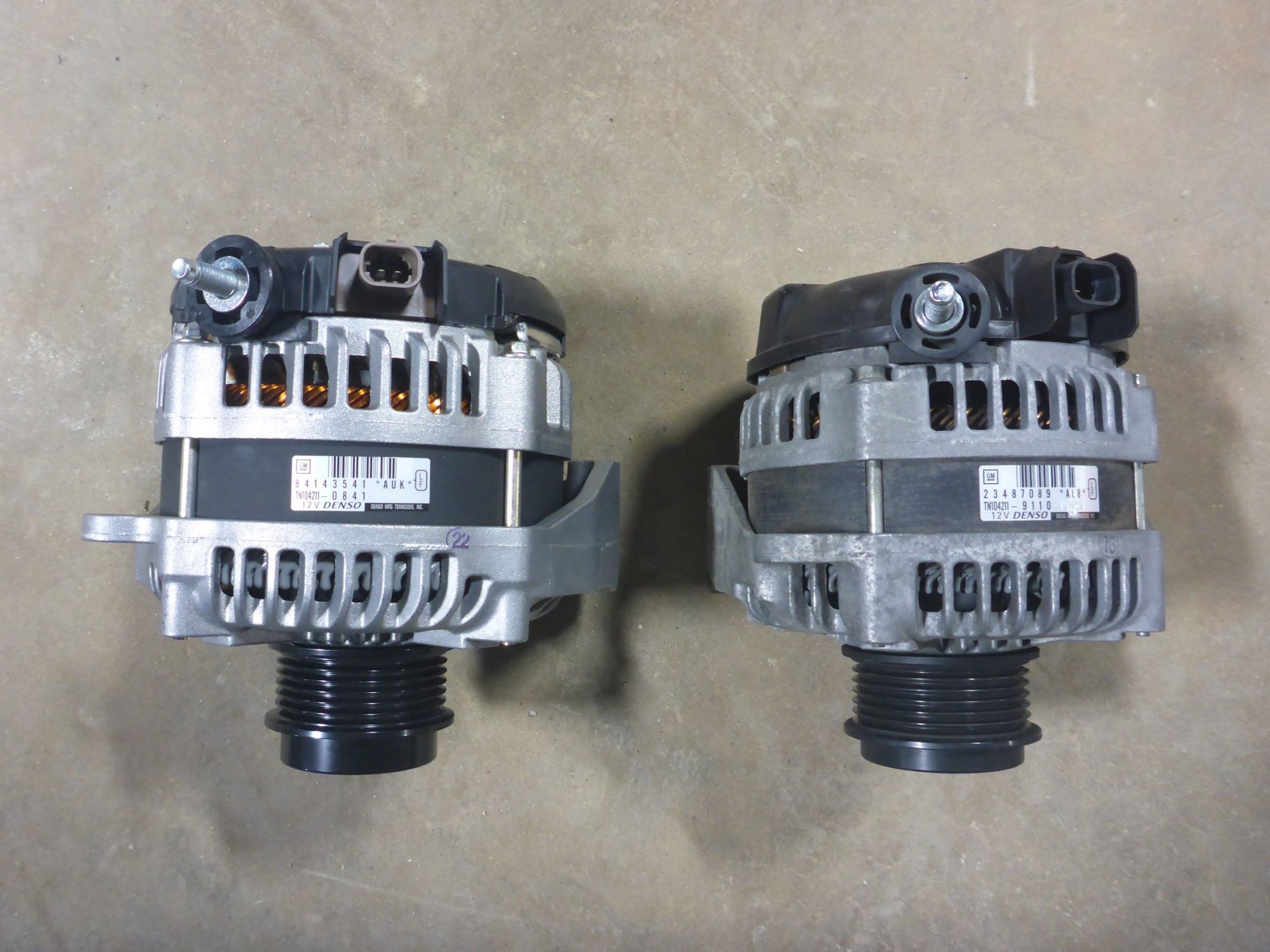
I've never seen the different pulley types but I haven't seen many of these trucks' engines either. Best I can do is attach my photos of part numbers I was referring to above. 150Amp mounted: 220Amp out of the box: 150Amp and 220Amp side by side: By the way, the 220Amp alternator has been working well for me for months now.
-
Vuk changed their profile photo
-
Oh I see now, I failed to see that you only need series resistors if you use a different power supply for the external trigger circuitry. One board that you've shown should be enough for two switches - the two channels should be independent. You set a pulse on the CH1 trigger input, and the relay turns on; you set another pulse on the CH1 trigger input, and the same relay turns off; same holds for CH2. If the board doesn't operate this way then it may be faulty.
-
There are two types of latching circuits: 1. set/reset that require two buttons where one specific button is designated for setting (turning on), and the other one is designated for resetting (turning off) 2. toggling that require one button If you don't want further complications, you should utilize the toggling type. I am looking at your previous post with the Amazon item description and I think that is the toggling type. Do you have the recommended resistors wired in the circuit? If you have even tried the board without those resistors it may be damaged.
-
Very clean; I like to document things myself because it makes your life so much easier down the line. I wish there were a few spots like the AUX battery ? Mine is taken by the actual battery so I had to tuck my latching relays under the dash - it's not too crowded in there.
-
The individual indicator wires are grounds. The hot ends run together to the voltage regulator for brightness adjustment as far as I remember.
-
Weather and salt make the most difference; the frame coating is really not robust to all conditions across the US.
-
On the opposite side of what you are looking at is a tab that secures the connector housing with the lever. Insert a small flathead screwdriver from the wire entry side to release the tab and pull the housing away from the wires (it will slide out towards the opposite direction than the direction wires are coming in).


-
Forum Statistics
250.4k
Total Topics2.7m
Total Posts -
Member Statistics
342,750
Total Members8,960
Most Online
-
Who's Online 15 Members, 0 Anonymous, 1,630 Guests (See full list)