
aflesch
-
Posts
234 -
Joined
-
Last visited
Content Type
Profiles
Forums
Gallery
Events
Articles
RPO
Store
Blogs
Everything posted by aflesch
-
New 2014 GM Truck Recall Covers Electric Steering Glitch
aflesch replied to txab's topic in Troubleshooting & Recalls
Update: Dealership says the negative battery cable needs to be replaced to the tune of $300. GM customer service says that this MUST be a different issue than the recall fixed even though the symptoms are the same and they aren't going to pay for it. They gave me a $100 service voucher which they tell me isn't good to pay the diagnostic fee. Now I have to pay the $99 diagnostic fee plus a $35 loaner car fee just to pick my truck up without being fixed. The battery cable is $51 and I can replace it myself. This is not what I expect of a 3 year old vehicle with 47K miles. NOT happy with GM right now. Edit: Just picked up my truck and the technician's notes say that the battery cable distribution block needs to be replaced NOT the negative battery cable as the service advisor told me. The part number they list is 23375728. GMpartsdirect lists part number 23375728 but shows it as discontinued. That tells me that GM knows there was a problem with this part since they discontinued it and superseded it with another one. Since it causes the same symptoms that they issued a recall for, it should be covered under the recall. -
New 2014 GM Truck Recall Covers Electric Steering Glitch
aflesch replied to txab's topic in Troubleshooting & Recalls
Thanks @tistre1. I contacted GMC customer service this evening to document the issue and will be calling the dealership in the morning. Did you have to pay for the additional repairs out of pocket? -
New 2014 GM Truck Recall Covers Electric Steering Glitch
aflesch replied to txab's topic in Troubleshooting & Recalls
Add me to the list of trucks not fixed by the recall. The behavior changed but I still lose power steering. The reprogramming just makes it so that when the issue occurs it doesn't jerk the steering wheel out of your hand; you still lose power steering though. The issue occurs in conjunction with another wierd electrical issue: activating a turn signal cancels the cruise control. Neither issue occurs unless I have been driving for more than 45 minutes which tells me it's a temperature related issue. I have corrected the G218 ground issue and it didn't change anything. -
2016 SLT lights in 14/15 SLT/All Terrain almost done
aflesch replied to zmnypit's topic in Modifications & Accessories
So, I've been following this topic for a while and finally had some time to play around with a circuit to turn the DRL off when the turn signal is flashing. I have no idea what Gen5 is working on but I got this circuit to work in a simulator. V1 is the DRL switched power supply. V2 is the flashing signal in the light harness for the turn signal. The "Turn Cancel" switch is not an actual circuit item; I just used it to simulate the turn signal being shut off at t=10s. "Turn" is the turn signal LED R3 is the LED load resistor to prevent hyperflash. C1 is a capacitor that is charged by the turn signal every time it flashes. D2 prevents the capacitor from providing power to the turn signal LED when the flasher in in between flashes and after it is shut off. R1 controls the rate of discharge of the capacitor to be longer than the duration of the flash. This keeps the voltage to the base of the NPN transistor above the "on threshold" even when the flasher is in between flashes. R2 limits the emitter current of the transistor. As long as the "on threshold" is met, the transistor allows current to flow through the relay coil, disconnecting the DRL LED power supply. When the turn signal is turned off (simulated by opening the "Turn Cancel" switch at t=10s) the capacitor fully discharges and the transistor switches off, releasing the relay, and restoring power to the DRL LED. The TVS Diode prevents the high voltage spike generated by the magnetic field of the relay coil collapsing when it is turned off. -
Lower ball joint stuck in place!!! HELP!!!
aflesch replied to zach1990's topic in Ask A GM Technician
This isn't your knuckle but yours will have a spot just like that. Hit it as hard as you can with a 3-5# hammer. The ball joint is a taper fit and by hitting it that hard you will actually oval the hole and it will pop the taper loose. -
We just got about 300 truckloads of fill back behind the building where I work. I couldn't resist...
-
Is Your Gmt-900 Truck Or Suv Using Oil
aflesch replied to RyanbabZ71's topic in 1999-2013 Silverado 1500 & Sierra 1500
Vehicle info in sig. Went through 1.75 qts in 9800 miles on Mobil 1 Extended Performance. -
HELP with front brake pads that won't fit!
aflesch replied to mjmilford's topic in Ask A GM Technician
I have had this happen several times with Duralast pads on different vehicles. I always just take a die grinder to the pads until they slide smoothly. I've never had a problem doing that. Just make sure you lube your hardware to keep them from squeaking. Edit: The backing of the pad is a cast steel piece that is not machined. There are bound to be variations in the casting. -
I've only got 65k on mine so I can't speak to the mileage question. The rear diff cover has a reusable gasket that doesn't require any RTV or anything. The front diff doesn't have a cover just a drain plug and fill plug so no worries there either.
-
What did you do with your truck/shop today
aflesch replied to SarahsGMC's topic in The Off-Topic Bar
New Battery New Monroe Quick-Struts (60,000 mi on originals). Custom made 2" leveling kit. I love the way the truck sits now. And holy crap I didn't realize how bad the struts really were until I drove around the block with the new ones. -
What did you do with your truck/shop today
aflesch replied to SarahsGMC's topic in The Off-Topic Bar
Changed Fluids in: Transmission (New filter) Transfer Case Both Differentials Not looking good for the transfer case...Fluid was BLACK...It looked like 15000mi old motor oil. -
-
-
-
-
-
What did you do with your truck/shop today
aflesch replied to SarahsGMC's topic in The Off-Topic Bar
Gave it a fresh 6 qts of Mobil 1 Extended Performance and a Wix filter -
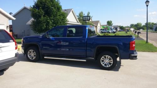
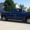
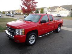
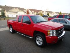
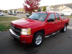
Finally a few pictures of my truck.

-
Forum Statistics
250.5k
Total Topics2.7m
Total Posts -
Member Statistics
342,873
Total Members8,960
Most Online
-
Who's Online 5 Members, 0 Anonymous, 596 Guests (See full list)