
-
Recently Browsing 0 members
- No registered users viewing this page.
-
Forum Statistics
250.4k
Total Topics2.7m
Total Posts -
Member Statistics
342,850
Total Members8,960
Most Online
-
Who's Online 4 Members, 0 Anonymous, 561 Guests (See full list)
-
Latest Articles
-
Posts
-
By 2016 Sierra Owner · Posted
I wouldn't want either of the 2 new gas engines until the next model year or 2. -
 My 24 ultimate I lose sound…no blinker clicks no radio no Onstar,nothing…have to take the key fob 75’ from truck till,it resets…that’s the fix…not so fun on road trips…dealership told me I was six updates behind…how when it’s been in the shop for a new alternator AND entire new high flow fuel system…spent weeks in the dealership and somehow I’m 6 updates behind? I dont think so. Now the transmission is giving me double hits as it engages in each gear witch means another trip to the dealership..not to mention gm can NOT build a decent duramax since they started making they're own version of the famous Isuzu motor…I’ve always been Chevy/GMC owner…but this….most expensive GM ever will be my last…I’ll be lookin for the dumbest truck I can find… Hey Mrs GM CEO…where’s the $15,000 full size truck ya promised two years ago? Failed? That seems to be GMs new motto… fake it till,it fails
 -
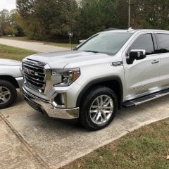
 Would you mind sharing your maintenance regiment and what brands of oils you have been using. For example engine oil change intervals and the specific type and viscosity used, fuel filter intervals, ( engine coolant, is one that tends not to get changed often enough ) diff oil type and interval, transmission pan drops if that is how you refreshed a portion of the oil, transfer case and anything else you happen to think of. By the way has the truck been on a lot of salty roads over these years and the first thing that shows up is the wax is gone on the frame from the rear of the transmission back and it isn't typically kind to brake life either which is why I was surprised how fantastic the brake pad life has been. Also if the park brake pads have been replaced as that has been discussed on here as per the rust belt area's cause the park brake shoe linings to fall right off.
 -
 Thanks for the feedback on my opening post, and wow, that truck has really treated you well. 🙂
 -
 sorry to bump an old thread, im a bit clueless with this stuff, would these fit a 2019+ Silverado? https://wiperpro.com.au/products/chevrolet-silverado-wiper-blades mainly wondering if the beam shape stays planted at highway speed, thats what seems to let the factory ones down imo
-
-
GM-Trucks.com Clubs
-

Black Truck Club
Open Club · 612 members
-

White Truck Club
Open Club · 380 members
-

Canadian Owners Club
Open Club · 282 members
-

Red Truck Club
Open Club · 157 members
-

diesel 3.0
Open Club · 281 members
-

Texas Owner's Group
Open Club · 371 members
-

NorthSky Blue Club
Open Club · 118 members
-

Midwest Owner's Group
Open Club · 213 members
-

2015 Custom Sport Club
Open Club · 5 members
-

GM Snow Plowing Club HD
Closed Club · 14 members
-
-
Popular Contributors
-
1
.thumb.JPG.2c573de60d3a3a4407c7d92298db46dd.JPG)
-
2

-
3

-
4
-
5
-
-

Recommended Posts
Archived
This topic is now archived and is closed to further replies.