

matt99199
-
Posts
64 -
Joined
-
Last visited
Content Type
Profiles
Forums
Gallery
Events
Articles
RPO
Store
Blogs
Everything posted by matt99199
-
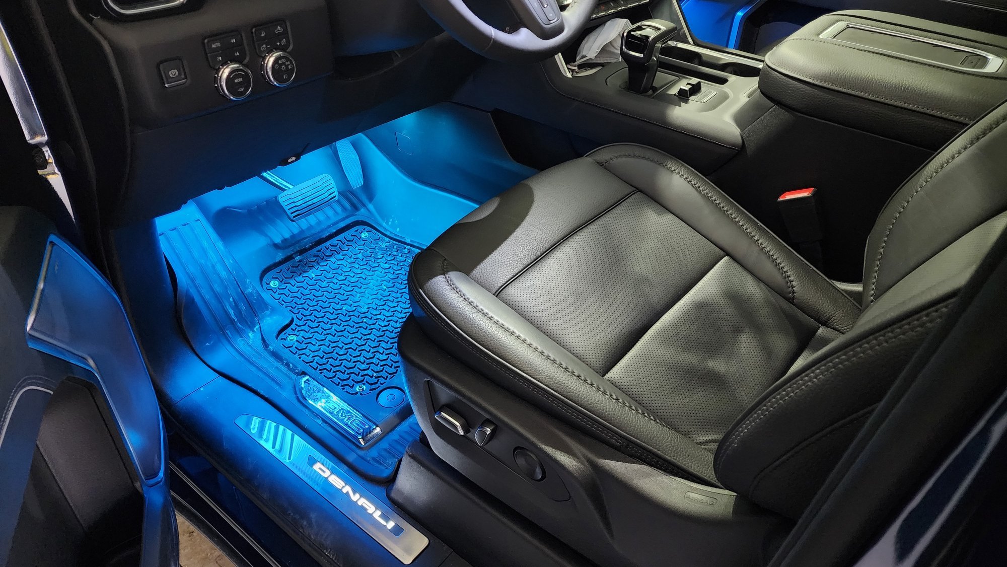
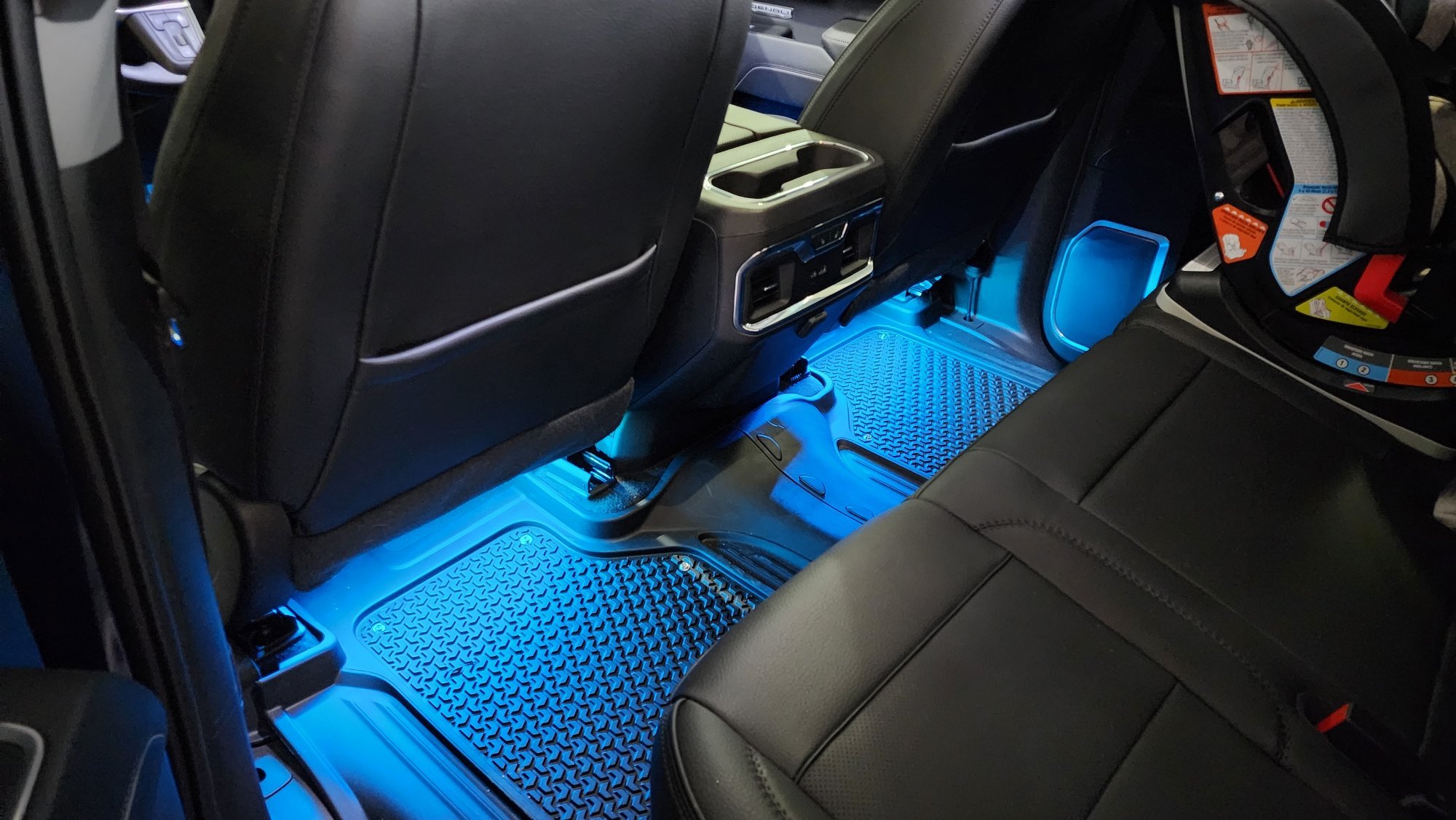
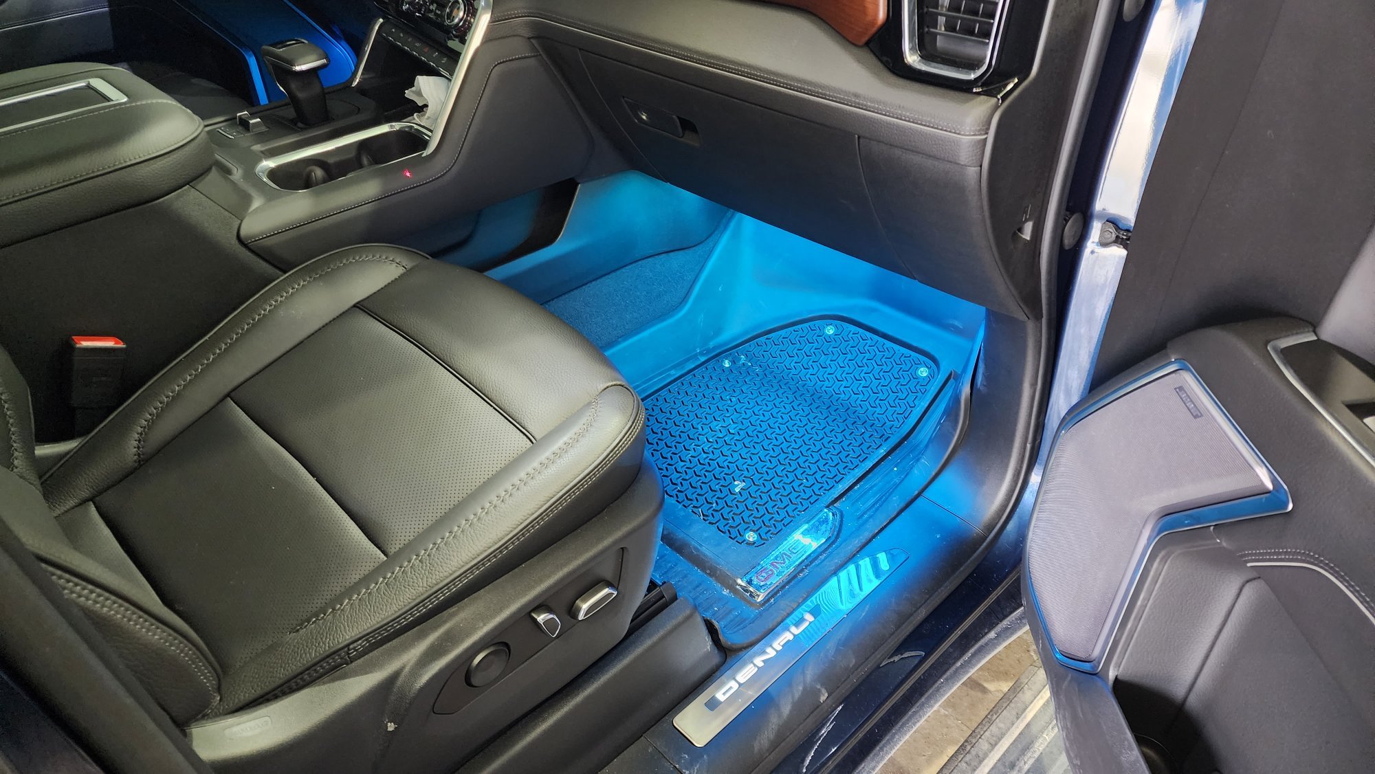
 Made it custom. I kind of took it to an extreme... I bought a known good company LED strip, wasn't happy with the LED current vs voltage performance (vehicle load dump voltages would have destroyed the LEDs over time), changed out all the SMD resistors to values I calculated, cut them to length along with some tick ABS plastic strips and mounted everything with zip ties. Also sprayed the strips with conformal coating to waterproof them. Then also hacked an existing RGB controller and added my own connectors that latch, did some other tweaks internally, etc. Kind of went overboard but they probably make kits that fit well enough. I could take pictures underneath if interested to show where and how I mounted them.
 -
This is how my install turned out, T tapped off of the door sills once installed and put RGB strip with a fancy controller for it all. Turned out great.

-
I found out Molex now allows you to buy the terminal if you are doing your own custom footwell lights, just FYI. https://www.molex.com/molex/products/part-detail/crimp_terminals/2000963101
-
Sorry all, for some reason I didnt have notifications turned on for my own post.... I'll share some finished product pics soon.
-
It may or may not click, the real test is if light force wont cause it to come out and if the locking tab reseats perfectly flush again to the connector housing.
-
After using this pin a while I can confirm its a 12V PWM dimmed signal. It may or may not be a good idea to use a relay with it as it could induce audible relay chattering. Probably OK but havent tested it. I ended up running my door sills and 4 seats of footwell lights no issue directly however.
-
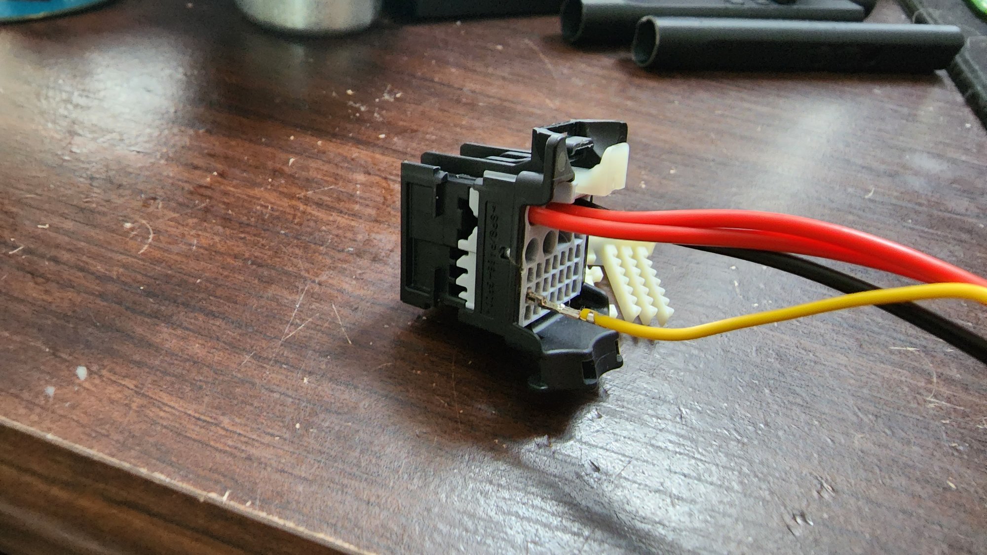
The picture was reference only on the process since I had another type easily accessible. These pins are sometimes very difficult to get that final push and may require a very small flat head to chase behind and drive home (or use some needle nose gently on the wire to put some force into it to get it to seat). Also make sure that locking tab is either fully removed or properly popped out enough. What can also happen is that raw exposed pin they have flapping around in the box can get ever so slightly bent and make it harder to insert.
-
Sorry for the late response but yes its that simple. Just getting to it is a pain and dealing with that locking clip.
-
2022 GMC Sierra 1500 Refresh HUD Optical Issues
matt99199 replied to matt99199's topic in Troubleshooting, Warranty & Recalls
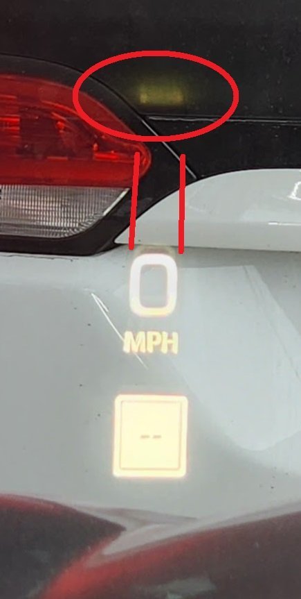
Anyone else check their huds for this faint glow/reflection? -
2022 GMC Sierra 1500 Refresh HUD Optical Issues
matt99199 replied to matt99199's topic in Troubleshooting, Warranty & Recalls
Trying to find where/who I can contact on the GM side to discuss all issues I've seen with my truck so far. My list includes: 1) The above. 2)Bluetooth/Android Auto cutting out once or twice per boot shortly after start - GM is aware of this and working to fix it (I know through connections). 3)Sometimes cellular connection to the truck glitches out and won't get data through (google assistant wont be able to do anything). And then it will complain about not having offline maps even though it has them downloaded. Might be a separate issue of google account loading improperly. 4) Some seldom laggy/freezing apps like navigation shortly after boot. 5) Multipro lockout feature doesn't activate/work. Maybe bad software in the module that controls it? 6) Forward collision assistance stopped working entirely once for me (pulled battery and rebooted, hasnt happened since). -
Just wondering if anyone else has bought a recent GMC Sierra platform with a HUD and if they have seen these "reflections" from inside the HUD. I worked at a different company that made HUDs and IPCs for GM, Ford, and others and know a bit of why this is happening. It's a surface somewhere on the inner mirror assemblies that isn't perfectly matte and is reflecting some light in an unintended path back onto the windshield. It's not the bezel at the top on the dash. Not super obvious but enough to annoy me. I find if I adjust the height just to the top where it starts to cut off, the anomaly gets cutout and removed but any head shift vertically will start to impact HUD image appearance. Maybe I just got a COVID unit....? Don't really want a dealership ripping my brand new truck apart but wondering if all HUDs have this (imo very low quality) issue. J
-
Part2.stp
-
Basically wired the three resistors, heatshrink wrapped them, tied with a zip tie internally and 3D printed a plug for the end. I made an ebay link if anyone wants to buy one. https://www.ebay.com/itm/234785652556 7pinplug.stl
-
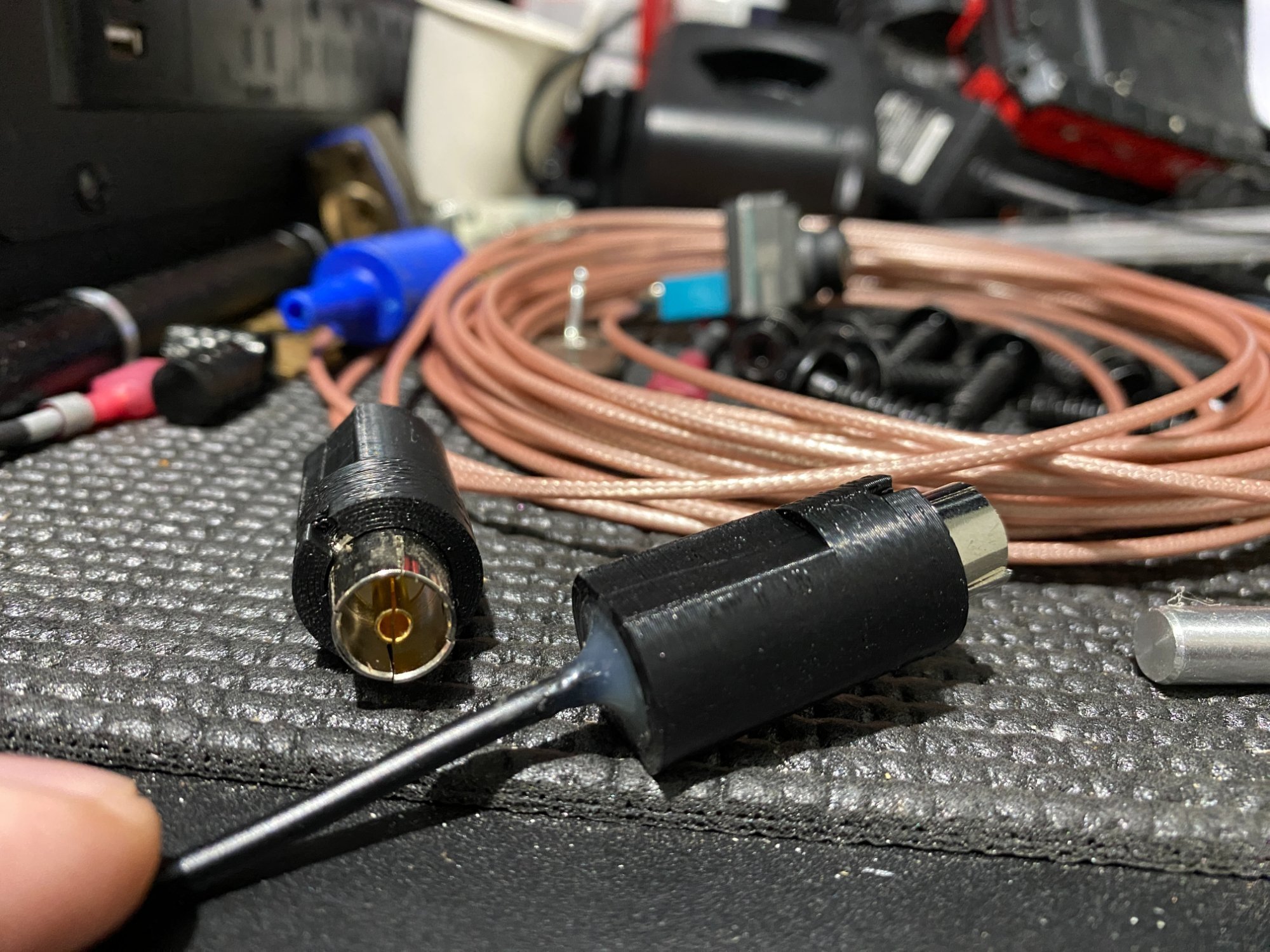
I got my version of this mod working and indeed you need to crimp the outer ring down more to make a firm connection for the ground. Just take some pliers and gently push two of the four tabs down. Worked even on my 10m cable. It's probably not "exactly" DVB-T but its close enough to work. I 3D printed some custom connector sheaths to protect the cable and slot into the port (attached). Just filled the ends with some high temp hot glue to make it solid. Will share my camera enclosure 3D model once I make it, trailer is packed away at the in-laws until spring though. I did this for fun for my boat trailer but might not actually mount it to that seeing that the thing goes under water....TBD, might make it water proof and go for it later. Also I made a fake trailer load to test this out since the truck didn't seem to want to switch to the camera view unless a trailer was connected and since my is put away I just ended up putting 3 75ohm 10W resistors in a 7pin connector breakout and it works. I can share details if anyone is interested or can make them for people and create an eBay link. This fake trailer load also allows you to see the lanes every time you use your turn signal like if you had the trailer attached; multi-purpose. Part2.stl Part2.ipt
-
Found that 75ohms or lower works to fool the truck into thinking you have a trailer with no light problems. You can buy a 7pin connector end without the wires and 3 75ohm resistors to wire from ground to right, left, running lights. Recommend 10W or higher metal resistors even 20W if they will fit (the more mass the better the heatsinking), I left them on for a while and they got up to 85C but still low enough to not melt the plastic connector housing. If anyone wants me to make one for them let me know and I can make a listing on eBay for a tiny bit more than material cost + shipping.
-
Typically you want to keep the total length from serializer and deserializer less than 15 meters but I cant say either way if it will still work or not. Testing vs actual use case vary. The problem is the multiple connectors in the path and cable loss at these high frequencies. Each connector on the path is an impedance discontinuity and loss of signal strength. The chipsets have some emphasis control and may work at these lengths but TI would have to comment. I wouldn't try introducing any more loss like a switcher however and keep it to only one continous cable. The other thing to consider which seems silly in the grand scheme is the DC power supplied over the coax too, cameras dont draw much but also have an operating voltage range and the longer the cable the bigger the voltage drop.
-
One thing that comes to mind is if you could find a coax or RF switch box. Not sure if it will be rated for FPD III speeds since they can operate up to 3.75Gbps IIRC but keep that maximum bit rate in mind, good luck!
-
I'm looking at doing this to test the "poor man's trailer camera" mod on this forum. Seems the truck will recognize a trailer if there is any <100ohm load on the trailer lights, right or left light pins but it doesn't like the load I have now and is throwing errors. Just using some 10W chunky metal housing resistors. Still trying to find what current won't throw an error on the DIC but my guess is it will be around >350mA per pin to think it has a genuine trailer connected. Problem is 0.35A * 12V = 4.2W per line to dissipate in just heat is kind of crazy and will probably melt a plastic housing if not properly heatsinked Turn signals aren't a concern since they are seldom used, pulsed, and not on for long but the running lights and brake lights (left and right ON) pose the problem. Not a problem for quick tests but probably not something you want to plug in just to override the software to allow use of the camera views while turning. Will keep you all updated if I find a proper value and something that can work 24/7, either way you would have a 7pin connector stub always inserted...
-
It would work with a BNC cable but as I said in the post above, it's not analog 75ohm style camera system. It's a 50ohm impedance system so if your wire was 75ohm it will have to be re-ran.
-
It's not an analog signal any longer, these cameras operate on TI FPD Link III and it's a pretty sensitive protocol. Signal integrity and impedance matching is very important.
-
2022 Chevrolet Silverado new body style has no 12V DC outlet.
matt99199 replied to JS1's topic in Future GM News & Rumors
There didn't seem to be any other local 12V lines in the area of the center console to tap off of but you could easily run a fuse tap off of the driver side fuse box and fish it above the footwell and through the center console trim to get back there. -
Update: With my door sills also installed and ON, the total current I could pull before a trip occurred was 2.48A. Safe bet is the tripping point could be anywhere near 2.5A on the pin with tolerances on top of it so I wouldn't draw more than 2A if you use this pin. Might want to consider a relay if driving any large amount of LEDs or load. I want to put under glow lights later on when you open the door so you can see where you step (got those GMC puddle lights that only look cool but don't work to watch where you are going) so I will be installing a relay at some point. I asked Molex about the terminal and they don't want people buying them for personal use as I figured, bummer.
-
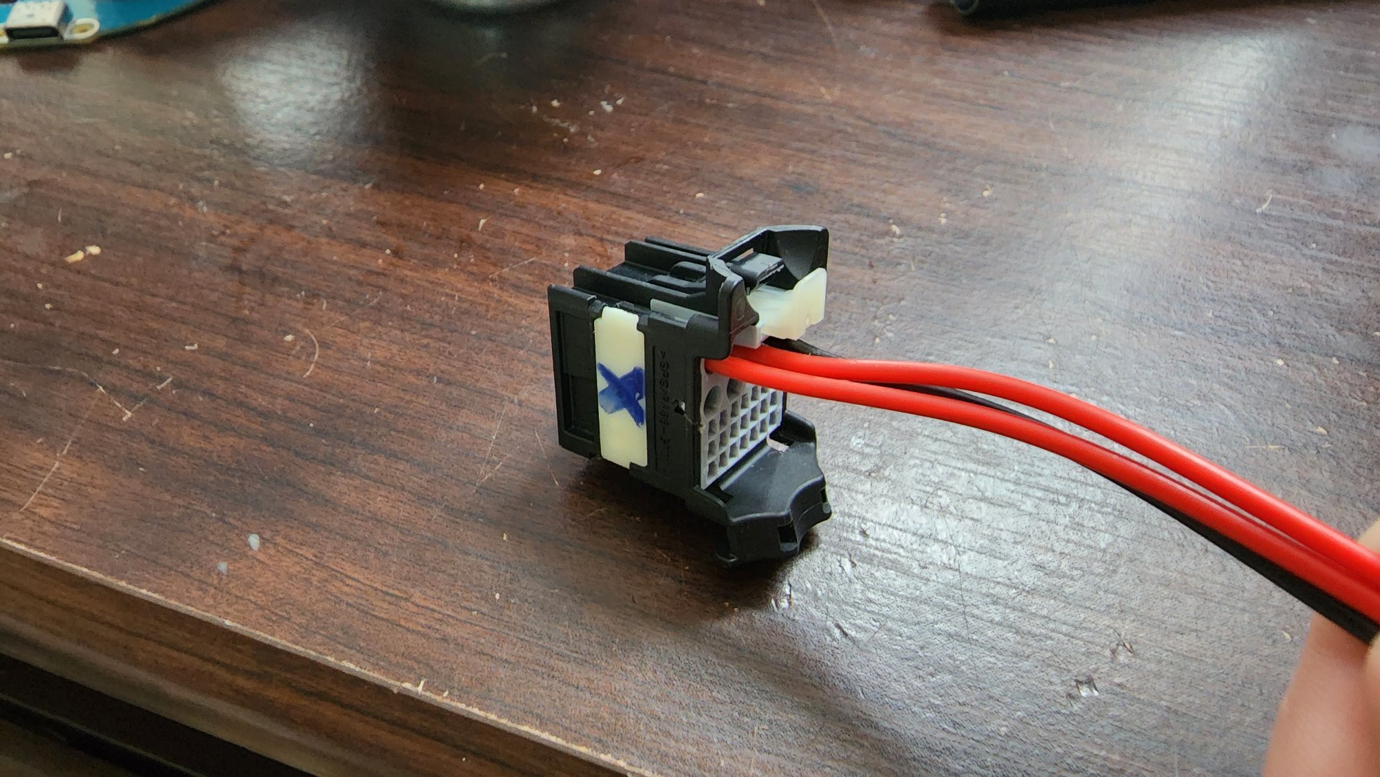
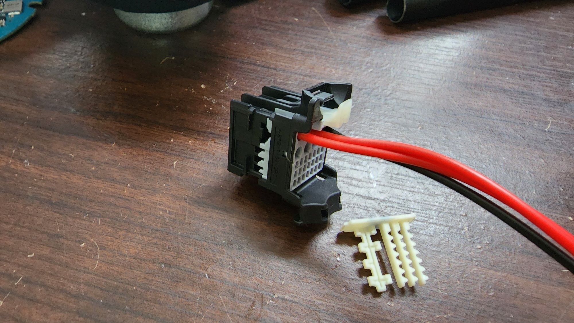
It's just a terminal pin, basically you take your existing X1 connector out, pop off the side locker for the pins (be careful not to break it, its fragile), orient the new pin with the smallest part of it facing up (if connector is facing up also), push it in until you hear a very faint click or you cant pull it out with low force, reinsert the side locker and plug it back in. The connector below isn't the one in the car but it gives you the idea.
-
Below is the link to an ebay listing if anyone wants the terminal wire stub to tap into their BCM as well. https://www.ebay.com/itm/234732009309 Still working on load testing the pin and contacting molex for alternatives.
-
Also it's a ****** to get to this last connector since its against the firewall. Recommend to remove the door-footwell trim kick panel that you scuff your free across to get in to gain better access to the BCM (like you would if you were installing the denali door sill light panels).


-
Forum Statistics
250.4k
Total Topics2.7m
Total Posts -
Member Statistics
342,749
Total Members8,960
Most Online
-
Who's Online 35 Members, 1 Anonymous, 1,757 Guests (See full list)
- Kevin Van Meter
- anthony2558
- KARNUT
- Barney26
- djv1951
- Dusilligaf
- cz2653
- dawsonar802
- MikeBMW
- BuckWallace
- OnTheReel
- Solo3937
- NDKoze
- Phase3
- PunchT37
- Black02Silverado
- georman
- BuysLumber
- Jake87
- Catchme2003
- NeilP
- bdup
- Steve-2019
- J69759623
- SierraStorm21
- mmey4
- GAMark
- Spendit
- JW2024
- Samari21
- mikeyk101
- JimMLINY
- parthery
- MrChips
- newdude