-
Recently Browsing 0 members
- No registered users viewing this page.
-
Forum Statistics
250.4k
Total Topics2.7m
Total Posts -
Member Statistics
342,844
Total Members8,960
Most Online
-
Who's Online 7 Members, 1 Anonymous, 799 Guests (See full list)
-
Latest Articles
-
Posts
-
 +1 for the 3.0 Perfect for 1500 pickup towing duties. Perfect engine for a 1500 pickup period. Huge torque at stunningly low RPM makes it feel a lot lighter than it is. The fuel mileage is insane for a tall and heavy 1500... 30+ on the highway. Mid 20's around town. It's probably not perfect if you bought a 6.2 for the braaaaaaapppppp V8 noises and wrapping it out to 6k. The LZ0 acts and sounds like a small turbo diesel and there's nothing you can do to make a small turbo diesel sound like a big one, and you can't make an inline diesel sound like a V8 diesel/big Duramax. It's a different driving experience altogether. Drive one, I think you'll like it, though...
 -
 I'll bet your truck lost the bearings on a roller on 1 of the lifters, and now is wiping out a cam lobe.
 -

By sigmonster · Posted
2024 2500 gasser with 47,000 miles. Driving on interstate Friday when my truck shudders, downshifts, and I get the above message with check engine light. Transmission would not upshift. I had to drive home 2 hours at 65 mph at 3600 RPM with transmission temps 190-200 degrees. Got it to the dealer Monday. They ran the code and said the #1 valve body was malfunctioning in the transmission. Miraculously, they had the part in stock and I had a new valve body installed that day with new transmission fluid/filter. Thankfully, all under warranty. Shout out to Everett Chevrolet in Hickory, NC. -
 Same I wipe down the engine bay every oil change.,
 -

By No F-bdy Bs · Posted
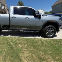
My truck rarely sees a dusty, dirt road, if ever. Actually, never. Within 6mo of ownership, mine was totally covered with road dust and yellow, Louisiana pine pollen. I swear, it looks 6yrs old. You'd think it was an oilfield, or pipeline service truck. Did GM just do a piss poor job of sealing the bay? Anyone else with this issue?
-
-
GM-Trucks.com Clubs
-

Black Truck Club
Open Club · 612 members
-

White Truck Club
Open Club · 380 members
-

Canadian Owners Club
Open Club · 282 members
-

Red Truck Club
Open Club · 157 members
-

diesel 3.0
Open Club · 281 members
-

Texas Owner's Group
Open Club · 371 members
-

NorthSky Blue Club
Open Club · 118 members
-

Midwest Owner's Group
Open Club · 213 members
-

2015 Custom Sport Club
Open Club · 5 members
-

GM Snow Plowing Club HD
Closed Club · 14 members
-
-
Popular Contributors
-
1
.thumb.JPG.2c573de60d3a3a4407c7d92298db46dd.JPG)
-
2

-
3

-
4

-
5
-
-

Recommended Posts
Archived
This topic is now archived and is closed to further replies.