
-
Recently Browsing 0 members
- No registered users viewing this page.
-
Forum Statistics
250.4k
Total Topics2.7m
Total Posts -
Member Statistics
342,803
Total Members8,960
Most Online
-
Who's Online 5 Members, 1 Anonymous, 960 Guests (See full list)
-
Latest Articles
-
Posts
-
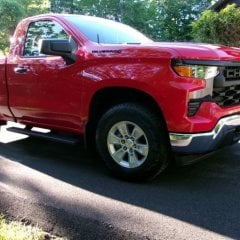 Your truck lowered, looks good. I'm happy with the stance on this. I may need the extra ground clearance given my location/situation.
 -
 With this new pan, do you still use the same procedure to check the level? Its a deeper pan and our trucks do not have a fill tube/dipstick. So fill till fluid runs out the check plug?
 -
.thumb.JPG.2c573de60d3a3a4407c7d92298db46dd.JPG)
By Grumpy Bear · Posted
On mine? Yes. But I did it rather expensively. I had Deaver Springs make new rear springs with a 2" lower arch and then removed the nearly 2 inch thick spring to axle spacer. The front is Bell Tech 2" drop knuckles. Rear shocks, stock, were several inches over mid stroke so when I bought the King shocks I used the OEM length with the drop to put it at dead mid stroke. Fronts are King Coil Over OEM replacements with 600# springs. Again sits mid stroke. Deaver, King Suspension and Ben at Filthy Motorsports were all involved. Lots of measurements and lots of conferences but it came out spot on first time around. The 2" I link I sent you would use the factory shocks and coil overs or any other OEM type replacement units you like. I assumed from your thread that keeping the factory feel and ride quality was likely. My project intended to change the very nature of the beast and it did. -

By Black02Silverado · Posted
Yes back when all the stuff started in Iran. Had a small price increase, then another one. Supposedly temporary. But who really knows for sure as long as there is turmoil in the middle east. -

-
-
GM-Trucks.com Clubs
-

Black Truck Club
Open Club · 612 members
-

White Truck Club
Open Club · 380 members
-

Canadian Owners Club
Open Club · 282 members
-

Red Truck Club
Open Club · 157 members
-

diesel 3.0
Open Club · 279 members
-

Texas Owner's Group
Open Club · 371 members
-

NorthSky Blue Club
Open Club · 118 members
-

Midwest Owner's Group
Open Club · 212 members
-

2015 Custom Sport Club
Open Club · 5 members
-

GM Snow Plowing Club HD
Closed Club · 14 members
-
-
Popular Contributors
-


Recommended Posts
Archived
This topic is now archived and is closed to further replies.