
-
Recently Browsing 0 members
- No registered users viewing this page.
-
Forum Statistics
250.3k
Total Topics2.7m
Total Posts -
Member Statistics
342,679
Total Members8,960
Most Online
-
Who's Online 6 Members, 0 Anonymous, 595 Guests (See full list)
-
Latest Articles
-
Posts
-

By asilverblazer · Posted
My interest isn't what is or isn't oil use, I'm interested in your measuring the use (or lack of) to compare to my own experience/measurements. -
 Cost me just under $3k to fill all 3 of my #2 tanks. That place was more than .50 cents a gallon cheaper than everyone else. I'll be set for a while.
 -

-

-

-
-
GM-Trucks.com Clubs
-

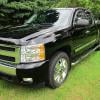
Black Truck Club
Open Club · 612 members
-

White Truck Club
Open Club · 380 members
-

Canadian Owners Club
Open Club · 282 members
-

Red Truck Club
Open Club · 156 members
-

diesel 3.0
Open Club · 279 members
-

Texas Owner's Group
Open Club · 371 members
-

NorthSky Blue Club
Open Club · 118 members
-

Midwest Owner's Group
Open Club · 212 members
-

2015 Custom Sport Club
Open Club · 5 members
-

GM Snow Plowing Club HD
Closed Club · 14 members
-
-
Popular Contributors
-

.thumb.JPG.2c573de60d3a3a4407c7d92298db46dd.JPG)

Recommended Posts
Archived
This topic is now archived and is closed to further replies.