
-
Recently Browsing 0 members
- No registered users viewing this page.
-
Forum Statistics
250.4k
Total Topics2.7m
Total Posts -
Member Statistics
342,759
Total Members8,960
Most Online
-
Who's Online 9 Members, 1 Anonymous, 2,158 Guests (See full list)
-
Latest Articles
-
Posts
-
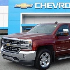
 The truck had about 10,000 miles on it when I purchased it in the fall of 2020 for about $31000. KBB seems to think it's worth between $20 and $25k now, assuming a good transmission.
 -

-
-

By SFC Retired · Posted
Picked up the liners yesterday. Installed passenger side WITHOUT any modifications. All mounting holes lined up perfectly. Rain is interfering today with drivers side. Very Happy! Will add pics when finished -

By Jus Cruisin · Posted
I'll be buying another 3.0l when I replace my 2025 Sierra. I had an issue (engine siezed) but it was replaced and has been fine ever since. I'm spoiled with the excellent fuel economy to swap to a 6 2l or its replacement.
-
-
GM-Trucks.com Clubs
-

Black Truck Club
Open Club · 612 members
-

White Truck Club
Open Club · 380 members
-

Canadian Owners Club
Open Club · 282 members
-

Red Truck Club
Open Club · 156 members
-

diesel 3.0
Open Club · 279 members
-

Texas Owner's Group
Open Club · 371 members
-

NorthSky Blue Club
Open Club · 118 members
-

Midwest Owner's Group
Open Club · 212 members
-

2015 Custom Sport Club
Open Club · 5 members
-

GM Snow Plowing Club HD
Closed Club · 14 members
-
-
Popular Contributors
-


Recommended Posts
Archived
This topic is now archived and is closed to further replies.