Jump to content

Recommended Posts

Posted

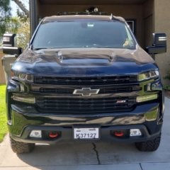
I have a 2020 Silverado Trail Boss. When I bought it I ordered the GM Accessories Sport Bar and had the dealership wire it into the truck. Several weeks later I was able to afford the light bar sold through GM Accessories, but it's made by Baja Designs. Unlike the previous generation of Silverados, this setup doesn't come with a new headlight switch for the dash. Instead they utilized a 2nd key fob. I wasn't happy about this, and decided I wanted a switch.


I thought it would be a good idea to use the GM Upfitter auxiliary switches. Talking to Baja Designs they said I'd need to swap the remote control receiver box in the wire harness for another harness that they have in stock because Ford trucks use the same lights and install to the auxiliary switches. I bought the harness, and it was shipped for only $15 total. I then also ordered the 9L7 GM Upfitter switches and started discussing with Baja Designs how this light would work, and the difference in functions between the key fob and a switch.


Unlike with a key fob, there's 2 settings. Full light, and low (75%) light. According to the guy I was talking to, full light requires only 1 switch, and requires more than 25 amps (but less than 30 amps). Low light needs less than 25 amps, but requires a 2nd switch and a ground. It was decided the light bar would be installed to switches 2 and 3, and the work commenced. It didn't take long to discover problems, such as the amount of cable being pulled through the firewall, plugs not matching up (both the lightbar and new harness that was ran to the Upfitter switch were female weatherpack), etc. I switched the weatherpack connector from the remote signal receiver to the new harness. I thought I'd overcome every obstacle until it came time to start the engine.


*Click*. That was all I got from my truck when I pushed the ignition button. After going through some troubleshooting I figured the issue is a weak battery. I managed to get a jump start, and went for a drive, eventuality ending up at the batting cages so my son could practice. After batting practice we loaded up into the truck and tried to start it. *Click* was all we heard again, and the wait for roadside assistance began a 2nd time.


I'm a bit frustrated, and clearly I'm over my head. After discussing the matter with somebody they told me I need a relay. I'm attaching the diagram. If anybody knows exactly what this is called, a link with a part number, etc it would be greatly appreciated. I'm also attaching pics of the 9L7 switches electrical diagram, and the wiring diagram Baja Designs sent me. On page 1 of the GM Upfitter schematic I connected the black wire to wire 966 (grey/black) using a quick slice Baja Designs supplied. Same was done to the green wire, but it's connected to 967 (brown/white, iirc). I ran black to a bolt on the body to ground it.


Did I do everything correctly? If not, what did I screw up on? Somebody has already told me I need a relay, and linked me to it, but I can't seem to find an actual product like the drawing. Do I avidly need the relay? What exactly is it? Where can I find it? How do I connect it?


Any and all help would be appreciated. Thanks in advance. Please ask any questions you may have. I'd really like to get my truck back in the road. It's a fun truck to drive. 9160327b910da6dbc3e49612011acb5e.gifbc568e0e2574e4542ca7e73a082e631c.jpge8dad33e13999551e17771953bd615f2.jpg6658b29035edcd9ab38bdea734f8847e.jpg305c76f8728f0769b0a83a99ca451d58.jpg


Sent from my SM-N960U using Tapatalk


Posted

I'd like to try to help, but not sure if my ideas will be good oe bad. 


First thing is I don't think you should require any extra relays as the up fitter switches already have them built in. One for each switch.

The wires coming out from the upfitter switches are fused as you know and supply positive power to whatever accessories you w ant to connect to them. Try connecting a test light to the  wire you are connecting to and make sure it is properly controled by the aux switch you intend to use.

In your post you didn't mention where you connected the white wire. You did say that you connected the black wire to wire 966 (grey/black) using a quick slice Baja Designs supplied and then later that you attached black to ground. Just need to confirm where the black is actually connected, because it shouldn't be connected to any switch wires.


I'm not able too see the wire  numbers in your attached pics, but will go get my print outs to double check which wire comes from which switch. 


Posted (edited)

Did some research and I find that switches 2 & 3 are both 20 amp circuits. Switches 1 & 4 are 30 amp. Switch #1 is the blue wire number 965 and switch #4 is the yellow/brown wire number 968.

Again, use a test light to confirm. 

The green wire confuses me. It looks like it goes through a switch and then to ground.  If that's the case,  then it should not go through the upfitter switches.  Can you post a better picture of the wire diagram from Baja? 

Edited by 20gmctruckguy
Typing error
Posted

I'm sorry. I made a mistake in my post. I said I connected the black wire to 966 (switch 2), green wire to 967 (switch 3), and the black wire to a ground. What I should've said was the white wire to 966. Both the white and green wires were connected via quick slice connectors provided by Baja Designs. Here's a link to the actual wire harness. The picture is missing the quick slice connectors on the end of the green and white wires, but they were already attached when I received the harness.


https://www.bajadesigns.com/products/ford-upfitter-wiring-harness-onx6-s8.asp


Sent from my SM-N960U using Tapatalk


Posted
Did some research and I find that switches 2 & 3 are both 20 amp circuits. Switches 1 & 2 are 30 amp. Switch #1 is the blue wire number 965 and switch #4 is the yellow/brown wire number 968.
Again, use a test light to confirm. 
The green wire confuses me. It looks like it goes through a switch and then to ground.  If that's the case,  then it should not go through the upfitter switches.  Can you post a better picture of the wire diagram from Baja? 
You stated switch 2 is both 30 amp and 20 amp. Did you mean switch 1 & 2 are 30 amp and switches 3-5 are 20 amp? Unless I email you the attachment I have of the Baja Designs wiring diagram, what I provided in the original post is the best I can do. I'm sorry. It's just a screen shot of what I have in my email.

Sent from my SM-N960U using Tapatalk

Posted
13 minutes ago, Transient said:

You stated switch 2 is both 30 amp and 20 amp. Did you mean switch 1 & 2 are 30 amp and switches 3-5 are 20 amp? Unless I email you the attachment I have of the Baja Designs wiring diagram, what I provided in the original post is the best I can do. I'm sorry. It's just a screen shot of what I have in my email.

Sent from my SM-N960U using Tapatalk
 

I realized my mistake later and have edited it. #1 & #4 are 30 amps.

Posted
I realized my mistake later and have edited it. #1 & #4 are 30 amps.
Ok, so there's 1 mistake I made. I'll move the white wire to switch 1 and the green wire to switch 2. I'm not sure why this is draining my truck's battery though. Thank you for your help. It's very much appreciated.

Sent from my SM-N960U using Tapatalk

Posted
13 minutes ago, Transient said:

Ok, so there's 1 mistake I made. I'll move the white wire to switch 1 and the green wire to switch 2. I'm not sure why this is draining my truck's battery though. Thank you for your help. It's very much appreciated.

Sent from my SM-N960U using Tapatalk
 

Can you post a picture showing the intructions and diagram from Baja Designs. I can't zoom in enough without making it blurry! Don't connect the green wire to any of the upfitter switches.  I'm thinking that might be a mistake but want to see the instructions more clearly. 

Posted
Can you post a picture showing the intructions and diagram from Baja Designs. I can't zoom in enough without making it blurry! Don't connect the green wire to any of the upfitter switches.  I'm thinking that might be a mistake but want to see the instructions more clearly. 
What I'm attaching in this post is the best I can do with my phone. The first attachment is the whole document. The remainder are zoomed in portions of that document. If this doesn't work, please send me your email via private message and I'll forward you the document. The firstde94c6b84fba73a05f15a70d6fe7782a.jpg140cd5e23fae499183857cb14076683c.jpg4a29ec728fd39b937a3836288b456656.jpgf3ae73e2a4358181353a46cb51ba2c22.jpg

Sent from my SM-N960U using Tapatalk

Posted

That's much easier to see! It looks like the green wire needs to be connected to ground via a seperate switch. It's like they are intending to take power "away" from the light in order for it to be in "low mode". 

I would suggest connecting the white wire to switch #1 and then install a seperate toggle switch into the green wire and then to ground (probably ground to the same spot as the black wire). 


You only need to connect to ONE of your upfitter switches.


Hope this works for you. 

Posted
That's much easier to see! It looks like the green wire needs to be connected to ground via a seperate switch. It's like they are intending to take power "away" from the light in order for it to be in "low mode". 
I would suggest connecting the white wire to switch #1 and then install a seperate toggle switch into the green wire and then to ground (probably ground to the same spot as the black wire). 
 
You only need to connect to ONE of your upfitter switches.
 
Hope this works for you. 
Yes. Thank you. I really don't need the lower light setting. I just thought it would be cool to have. Due to living in California, the light bar has stay covered while driving on road anyways.

Sent from my SM-N960U using Tapatalk

Posted

Just thought of something else. Did you move the 5 amp fuse in the upfitter relay box to the "switched" side? Mine came with the two 5 amp fuses install in the constant power position. When in the switched position there will no power to the accessories when the truck is off.

Posted

I did not. I'll have to check that. I'm letting my truck run right now to recharge the battery. I already changed out the connections as discussed earlier. Once I completed that I had to keep the battery on the jump box for several minutes before it was able to turn over the starter with the help of a jump. The lightbar still isn't lighting up with the engine running. Baja Designs said it has a processor that will prevent it from turning on if the battery is low, so I'm hoping that's the case.

Sent from my SM-N960U using Tapatalk

Posted

This just keeps getting more "interesting", and I'm even more stumped. I just disconnected both the positive and negative cables at battery for the light bar only. Prior to doing this everything worked, except for the starting not turning over and the lightbar not turning on. Now that I disconnected both the positive and negative connections to the lightbar from the battery, and disconnected the harness used to connect the auxiliary switches from the light bar main harness, I have no electricity in the truck. Jump box didn't detect the battery when I placed the positive clamp onto the positive terminal and negative clamp on the chairs ground post near the hood strut mount next to the battery. I moved the negative clamp to the negative post and it detected the battery, but still no electricity to the truck. Essentially, the lightbar is completely disconnected electrically, but it's the truck that has no electricity. It's as if the lightbar is supplying electricity to the truck. Here's what the fuse block on top of the battery looks like.78dcf6f119a1073f7385b7835c9475fb.jpg

Sent from my SM-N960U using Tapatalk

Posted

It's quite possible for you to have a faulty battery.  It happens quite often. Have you got a volt meter that you can see how many volts the battery is putting out? Shold be around 12.4 without the engine running and around 14 with engine running. 

Create an account or sign in to comment

You need to be a member in order to leave a comment

Create an account

Sign up for a new account in our community. It's easy!

Register a new account

Sign in

Already have an account? Sign in here.

Sign In Now
  • Recently Browsing   0 members

    • No registered users viewing this page.
  • Forum Statistics

    250.5k
    Total Topics
    2.7m
    Total Posts
  • Member Statistics

    342,881
    Total Members
    8,960
    Most Online
    tararebecca
    Newest Member
    tararebecca
    Joined
  • Who's Online   3 Members, 0 Anonymous, 538 Guests (See full list)

  • Latest Articles

  • Posts

    • I agree, simplicity and reliability matter more as vehicles get more complicated. A V8 work truck option with fewer electronic features and a stronger warranty would definitely appeal to a lot of buyers who use their trucks for real work. Customizing it with trusted outfitters is often the best way to get exactly what you need.webcrimsNY
    • I’ve heard similar complaints from newer vehicles where the factory “premium” systems don’t always live up to expectations. A good installer should be able to improve the sound without turning it into a bass-heavy setup. I’d look into upgrading the front speakers, adding a quality DSP amplifier, and possibly improving sound deadening first—those changes usually make a much bigger difference than just adding a subwoofer. Hopefully someone local can recommend a reputable installer in the Las Vegas/St. George area.
    • Do you remember that Harley Davidson was more successful (solvent) when it produced about 60% of the market demand (by design) and forced wait times of up to three years? Even when your turn came around it was, "Take what we are giving you or move to the back of the line and start over". HUGE markup's were 'normalized' and dealer killed. 40% markup and no floor plan? What's not to love? Greed will kill them yet. They have surplus production and customer base is tanking. And still they think nosebleed pricing will work.  
    • The engine was done as part of the 6.2 recall?   You'd have to see if your VIN also has the 6.2 engine special coverage on it.  Coverage number is N252494003.  If you have this, your engine is covered under this and NOT the GM replacement part engine warranty which is 3yr/100k from the date of install.  The 3yr/100k mi warranty is in effect for non warranty purchases.     This is not any different if it was replaced under warranty without a recall or special coverage.  So if you had a 5.3 and it popped at 3 years in at 50,000mi during the 5yr/60k powertrain, the replacement engine would not get the 3yr/100k, and instead gets the remainder of the 5yr/60k as coverage.     So N252494003 gives 10 years or 150,000mi of coverage, which ever comes first, starting at the vehicle in service date.  So if your in service date is 01/01/2022, N252494003 gives you special coverage of the engine until 01/01/2032 or 150,000mi, whichever comes first.  So if your start date was 01/01/2022, you'd have left 5 years and 4 months (lets round to august 1st), or 62,000mi left of coverage.   So you need to know your in service date to know how much coverage is left.  
    • Okiee dokie there bud, way to take things to the extreme.   I guess you missed the whole point and take things way to serious. I installed different EV6 style injectors that just so happen to be larger in my car running the same LQ4 engine and with a better spray pattern than the stock style injectors and I noticed no difference in the idle quality. Kinda was my round about way of saying that even if you put the same size but better style injectors in your truck, you will likely see the same thing.    I'm sure you're great to have conversations with in person if that's how you act through a keyboard. One little things sets you off and now I guess my dick is all up in your face.
  • GM-Trucks.com Clubs

  • Popular Contributors

×
×
  • Create New...