-
Recently Browsing 0 members
- No registered users viewing this page.
-
Forum Statistics
250.3k
Total Topics2.7m
Total Posts -
Member Statistics
342,726
Total Members8,960
Most Online
-
Who's Online 7 Members, 1 Anonymous, 1,176 Guests (See full list)
-
Latest Articles
-
Posts
-

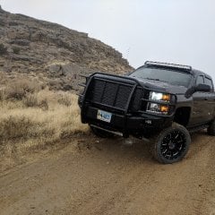
By No F-bdy Bs · Posted
Diesel or gas? The 37s will obviously, drastically reduce mpg, but the gasser will take a bigger hit to mpg, and power. Rough guess, but I'd estimate a wmpg hit on the diesel, and up to 4on the gasser. I wouldn't sweat a gear change on a duramax at all, and unlikely on the gasser either. You're obviously not concerned with acceleration or towing, and the 10spd will find itself in the right gear without much hunting, if any. If towing, mpg and acceleration are a concern, you're doing the wrong mods. Either leave it alone, or do the lift/tires and let the chips fall where they may. -
.thumb.JPG.2c573de60d3a3a4407c7d92298db46dd.JPG)
By Grumpy Bear · Posted
I understand. It is disturbing to think a manufacture asks so much and gives so little in engineering support. This is not a GM issues, this is a greed issue and one the ALL practice. My intent was not to remove the wind from anyone's sail but rather to point out the areas deficient so that they can be discussed with improvements the goal. But to do that you have to know the truth and what that truth is. The commercial interest are honed in on a few select issues in which they control all the variables and are not forthcoming in the least with their customers about the details. Failure is the only thing that drives these people to improvement. One way not to fail it to manage public "expectations". The set a bar they can clear and put their thumbs under the suspenders with chest puffed.... Only the internal data tells the story fully. As we don't have access to that for decades then we have to generate it ourselves. UOA's with data that matters. -
 I had skimmed through that article when you posted the link and honestly I felt rather defeated in a sense and realized that all these years in changing oil that in fact putting in what I was told was a good quality oil was probably not filtered as well as it should be although the filter put on the engine would be what ( as long as it never went into bypass mode ) would be the final filtering of the new oil that the engine components would first see, but then the filtering media itself is not up to par to what is ideal because a full flow filter would be too restrictive to filter fine enough for the engines best outcome in the long run. Only one of our tractors over the years which was a Versatile with a 855 Cummins had a separate bypass filter, some engine manufacturers did spec a partial bypass system within the main oil filter but I don't believe any other trucks or equipment I was servicing used such a filter. No doubt a product like the Amsoil bypass system is of benefit as long as nothing goes sideways with the extra plumbing and filter such as a rupture/leak that could cause the oil to pump out of the engine ( yes that Versatile had a remote canister with hoses routed to it as well ). With the idiot egr system on a diesel and as a result forcing a lot more soot into the oil, that certainly isn't helping the diesel engines cause or as you pointed out the GDI engine issue with creating more soot and aside from having a fancy secondary filtering system, changing the oil more often helping lower the total soot load. So oil manufacturing and the end product is not something one can control and I wonder if there are specs on what various oil packaging companies produce in particle count or size. As to the filtering, if the OEM is not designing a filter size and spec that is really what it could be, they too are short changing the end user and so what is the answer. Of course as you say the oil side can only do so much if the air side isn't keeping up its end of the picture and air filters are only so efficient and if in a dusty environment such as farm or construction or driving gravel roads there is a lot of dirt to filter out and some of that ends up into the air stream. Of course the irony in places like where I am where they dump the salt on the highways but also will mix in some calcium or outright pure calcium for problem road area's, or using calcium as dust control on gravel roads, the vehicle that gets used in that environment may rust out before a properly engineered engine and maintenance finally wears out so one has to face that reality in the rust belt.
 -
-
 have you stuck with dealer oil changes since then? I made the same switch after getting tired of crawling around under the truck, but I’ve found some dealers are way better than others about getting you in quickly. Curious if yours has been good about scheduling or if you’ve had to look elsewhere for quicker turnaround.
-
-
GM-Trucks.com Clubs
-

Black Truck Club
Open Club · 612 members
-

White Truck Club
Open Club · 380 members
-

Canadian Owners Club
Open Club · 282 members
-

Red Truck Club
Open Club · 156 members
-

diesel 3.0
Open Club · 279 members
-

Texas Owner's Group
Open Club · 371 members
-

NorthSky Blue Club
Open Club · 118 members
-

Midwest Owner's Group
Open Club · 212 members
-

2015 Custom Sport Club
Open Club · 5 members
-

GM Snow Plowing Club HD
Closed Club · 14 members
-
-
Popular Contributors
-


Recommended Posts
Create an account or sign in to comment
You need to be a member in order to leave a comment
Create an account
Sign up for a new account in our community. It's easy!
Register a new accountSign in
Already have an account? Sign in here.
Sign In Now