-
Recently Browsing 0 members
- No registered users viewing this page.
-
Forum Statistics
250.3k
Total Topics2.7m
Total Posts -
Member Statistics
342,701
Total Members8,960
Most Online
-
Who's Online 8 Members, 1 Anonymous, 528 Guests (See full list)
-
Latest Articles
-
Posts
-

-
-
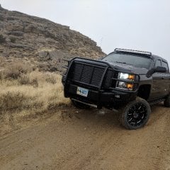
 Same no dirt roads, so I put it in 4hi on a straight stretch of road, set the cruise to 45, and go.
 -
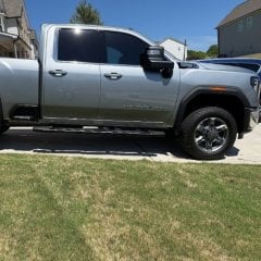
 ...but they do...currently...Chevy, GMC and Ford. Ford is the only one that has a V8 RCSB though...
 -
 Thanks for the info, ive decided to use only Chevron fuel from now on, the answer i was looking for since i posted this subject; Thanks to everyone for your input.
-
-
GM-Trucks.com Clubs
-

Black Truck Club
Open Club · 612 members
-

White Truck Club
Open Club · 380 members
-

Canadian Owners Club
Open Club · 282 members
-

Red Truck Club
Open Club · 156 members
-

diesel 3.0
Open Club · 279 members
-

Texas Owner's Group
Open Club · 371 members
-

NorthSky Blue Club
Open Club · 118 members
-

Midwest Owner's Group
Open Club · 212 members
-

2015 Custom Sport Club
Open Club · 5 members
-

GM Snow Plowing Club HD
Closed Club · 14 members
-
-
Popular Contributors
-
1
.thumb.JPG.2c573de60d3a3a4407c7d92298db46dd.JPG)
-
2

-
3

-
4

-
5
-
-

Recommended Posts
Create an account or sign in to comment
You need to be a member in order to leave a comment
Create an account
Sign up for a new account in our community. It's easy!
Register a new accountSign in
Already have an account? Sign in here.
Sign In Now