
-
Recently Browsing 0 members
- No registered users viewing this page.
-
Forum Statistics
250.4k
Total Topics2.7m
Total Posts -
Member Statistics
342,791
Total Members8,960
Most Online
-
Who's Online 6 Members, 0 Anonymous, 1,698 Guests (See full list)
-
Latest Articles
-
Posts
-
 Fix one problem and find another. Truck didn't have a thermostat in it so I flushed out the system today and refilled with 50/50 Dexcool. This truck is so old (LOL) that it has a sticker under the hood alerting people to the fact that it contains such. There is also an orange supplement with the owner's manual alerting the owner that "Your vehicle is one of a number of late production 1995 General Motors vehicles that use a newly developed engine coolant in the cooling system..." I was still a little flummoxed by what seemed like a rich condition (exhaust smell, and a puff of carbon with a punchy rev). While watching the coolant temperature and testing the thermostat with my scanner, I happened to notice the IAT (incoming air temperature) to the intake was -40F. I know the temp is below average today, but I can still feel my face, and I was wearing shorts. D'oh!! I realized I had never plugged the IAT back in, and the airbox was out while I was doing coolant. So I paused, reinstalled the airbox and plugged in the IAT, and viola. Things cleared right up, and I watched the coolant temp climb to a reported 198 degrees on the scanner (195 thermostat) and then it dropped to 194 (open) and then back up to 198 and held. Let it cool, came back, checked the coolant level and was satisifed. Victory lap? It needed more than the couple of gallons of gas I put in it from almost bone dry, so I ran it up to the gas station. It had earned it, or, at least I was pretty certain I wouldn't be draining or removing the tank anytime soon. CEL popped on just as I was cruising a nice steady 40mph, just after coasting down a slight downhill curve.. Of course, it did, because, why let me enjoy not having dash emojis for a little while. I just happened to have the scanner plugged in. I don't text and drive but I might scan and drive. Don't tell the police. P0401, EGR flow insufficient. Well, hello, EGR... ...my old friend! Welcome to the party, now that the engine reaches the factory-programmed operating temperature. I'm sure it was gagging on hostile, rich exhaust and carbon this whole time so I'll take it off and look again. At least it's easily accessible, and worst case, about $65 to replace. To keep, or to sell... Hmm. I want it running correctly either way. It's easier to sell when there are no fault codes. It needs tires (they're aged out and cracking) It could probably use an oil pan seal, or maybe the timing cover gasket/ junction with the pan needs redone because I've got an issue there that leaves a drop of oil on the floor. If I do tires I'm sure they'll say the ball joints could use freshening, and, and, and, and.... At some point I'll have to stop. I can't (shouldn't) make it perfect, that's not what this rig is.
 -

-
 Gloss black would look better, but I'd paint match the grill before ditching the chrome bumpers.
 -
 Mine has done that since new. The colder the worse.
 -
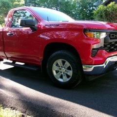 Yeah, that's my understanding. The newer trucks are 433Mhz vs the older 315Mhz TPMS. Putting these wheels on is costing me a small fortune, but so far, I'm still OK with it. Next week the chrome bumpers are scheduled to be replaced with flat black ones. That would complete what the dealer still owes me.
-
-
GM-Trucks.com Clubs
-

Black Truck Club
Open Club · 612 members
-

White Truck Club
Open Club · 380 members
-

Canadian Owners Club
Open Club · 282 members
-

Red Truck Club
Open Club · 156 members
-

diesel 3.0
Open Club · 279 members
-

Texas Owner's Group
Open Club · 371 members
-

NorthSky Blue Club
Open Club · 118 members
-

Midwest Owner's Group
Open Club · 212 members
-

2015 Custom Sport Club
Open Club · 5 members
-

GM Snow Plowing Club HD
Closed Club · 14 members
-
-
Popular Contributors
-
.thumb.JPG.2c573de60d3a3a4407c7d92298db46dd.JPG)

Recommended Posts
Archived
This topic is now archived and is closed to further replies.