

-
Recently Browsing 0 members
- No registered users viewing this page.
-
Forum Statistics
250.4k
Total Topics2.7m
Total Posts -
Member Statistics
342,840
Total Members8,960
Most Online
-
Who's Online 15 Members, 1 Anonymous, 537 Guests (See full list)
-
Latest Articles
-
Posts
-
 // Thank you, also for your response. More information is always good. This 2013 GMC is most likely my 'forever truck"-I'm 77 and retired...and truck only has 42K on it-very clean-so I try to keep it that way. Tks again for your response- glenn
 -
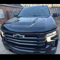 I started my install this weekend. Everything was pretty straight forward but I ran into one issue with running power through the firewall. The nipple grommet on my High Country already has a small harness running through it - has anyone else ran into this issue? And on the engine bay side, does the wire basically just penetrate the factory wiring boot? I did this on my '22 Trail Boss and it seems much easier but thats been a few years. My other thought would be possibly drilling a new hole adding a rubber grommet just to the lower left of the factory hole. Thoughts? Has anyone used a T-harness off the Bose amp and obtained power from there? It seems a little odd that such a small amp needs 3 power leads
 -
///// Ok--Thanks for that info--I could not find yesterday when I looked for the specs on that NAPA filter what I wanted. Their website is not very user friendly. I buy all teh filters for our three vehicles once or twice a year. Have always run NAPA Gold on everything I own....I buy it thru my Son's account for his business-which he has a Heavy Equipment repair shop-one reason he uses NAPA so much-they have such a full line of coverage for just about anything/anywhere- He gets s good discount because of volume bought. Anyway-Thank you -Sir for your response. glenn
-
 It is possible to add your own 12v outlet to your truck. Check out this video: I verified via GM Upfitters that pin 31 is the same on the 1500 trucks. The wire is GM part number 84779405. You can get the GM 12v outlet from Amazon https://www.amazon.com/Genuine-Accessory-Receptacle-25774623-13549530/dp/B0F1H9YRGF EWAY 12 Volt Power Adapter for GM https://www.amazon.com/EWAY-Chevrolet-Silverado-Cigarette-Ignition/dp/B0915RRW6Q/ref=sr_1_1? I just haven't figured out a good place to put the 12v outlet in my truck. Some people are getting USB-C to 12V adapters https://www.amazon.com/WYMECT-Cigarette-Lighter-Socket-Adapter/dp/B0F87WNQKB/ref=sr_1_1_sspa? Not sure if they provide the correct amperage that a device like a tire inflator would need.
 -
 Thanks; I looked there a few minutes, and I think I can find something. I really never looked there, as I thought it was stuff like PTO/aftermarket bodies/accessories like snow plows.
-
-
GM-Trucks.com Clubs
-

Black Truck Club
Open Club · 612 members
-

White Truck Club
Open Club · 380 members
-

Canadian Owners Club
Open Club · 282 members
-

Red Truck Club
Open Club · 157 members
-

diesel 3.0
Open Club · 281 members
-

Texas Owner's Group
Open Club · 371 members
-

NorthSky Blue Club
Open Club · 118 members
-

Midwest Owner's Group
Open Club · 213 members
-

2015 Custom Sport Club
Open Club · 5 members
-

GM Snow Plowing Club HD
Closed Club · 14 members
-
-
Popular Contributors
-
.thumb.JPG.2c573de60d3a3a4407c7d92298db46dd.JPG)




Recommended Posts
Archived
This topic is now archived and is closed to further replies.