-
Recently Browsing 0 members
- No registered users viewing this page.
-
Forum Statistics
250.4k
Total Topics2.7m
Total Posts -
Member Statistics
342,869
Total Members8,960
Most Online
-
Who's Online 14 Members, 0 Anonymous, 661 Guests (See full list)
-
Latest Articles
-
Posts
-
 Given your chart GB, and the anecdotes we've seen here of what I think were 10L80 transmissions running consistently at 200 degrees and higher under light-ish towing loads I'm very pleased that mine stays around 145, even in high ambient temps. Of course the proof will be in the pudding when I actually pull one of my trailers, but at this point it appears that I won't see temps in the "dangerous" ranges for my tranny.
 -
.thumb.JPG.2c573de60d3a3a4407c7d92298db46dd.JPG)
By Grumpy Bear · Posted
Sleeve bearings have been about a thou per inch of diameter for over a hundred years. Piston clearances have changed back AND forth. I've heard there is a new forging alloy that can be fit as tight as a cast piston. That would be big news for small inch boosted OEM's but would have nil effect on oil weight. Hypereutectic cast pistons have/are used in Harley Davidsons at a thou bore clearances and still use 20W50. Yep, allot of smoke and mirror marketing. Lower viscosity, lower AW levels (sacrificial chemistries) and longer OCI's depleting them. Toss in some poor QC not catching machining issues and it's amazing they lasted as long as they have. Side note. that 0W* v 5W* noise is just that. Noise. Unless you live where it's > -22 F constantly. Zero weight is another fuel play. It's actually the majority of the fuel savings in a light weight oil. In my zip code we've had two days in a decade that it has been the cold. On those days both Pepper and I call in sick. -
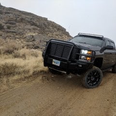
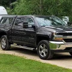 It sure does. You have to look a little closer. This is mine.
 -
 Total quoted repair cost from our local dealer.
 -
By Grumpy Bear · Posted
O2's not working well will alter the AFR and make em stink. Drop that cat in a bucket of hot soapy water then pressure wash the internals, what you can reach. Brings a good many of them back to life if it's soot and not poisoned.
-
-
GM-Trucks.com Clubs
-

Black Truck Club
Open Club · 612 members
-

White Truck Club
Open Club · 380 members
-

Canadian Owners Club
Open Club · 282 members
-

Red Truck Club
Open Club · 157 members
-

diesel 3.0
Open Club · 281 members
-

Texas Owner's Group
Open Club · 371 members
-

NorthSky Blue Club
Open Club · 118 members
-

Midwest Owner's Group
Open Club · 213 members
-

2015 Custom Sport Club
Open Club · 5 members
-

GM Snow Plowing Club HD
Closed Club · 14 members
-
-
Popular Contributors
-


Recommended Posts
Create an account or sign in to comment
You need to be a member in order to leave a comment
Create an account
Sign up for a new account in our community. It's easy!
Register a new accountSign in
Already have an account? Sign in here.
Sign In Now