-
Recently Browsing 0 members
- No registered users viewing this page.
-
Forum Statistics
250.5k
Total Topics2.7m
Total Posts -
Member Statistics
342,894
Total Members8,960
Most Online
-
Who's Online 5 Members, 0 Anonymous, 854 Guests (See full list)
-
Latest Articles
-
Posts
-
 Thanks! I figured as such; GM and other manufacturers have used standard parts and harnesses across trim levels and such for decades. I pulled the blank accessory cover off of my commuter van (a 2016 or so Chevy 15-passenger) years ago and found the plug for a USB outlet. It wasn't connected to anything, though (I tried swapping in an outlet from another van). I was a GM Tech years ago (late-90s) and was pretty familiar with my 2006. I might be wrong, but I view newer vehicles (pretty much anything made in the past 20 years) as being a lot more plug and play. Meaning, more unused wires and plugs unless you have the Mack Daddy of vehicles.
 -

-
 not all plugs will be used. gm uses more generic harnesses that support most/all options, and if your truck doesn't have a specfiic option, the plug won't be used (commonly will have a dummy insert in the plug , or it'll be taped up, but some may just be left as is). But it's sldo possible some p.o. has installed the wrong/cheaper parts that aren't correct for your vehicle...
 -
First off, I'm not trying to just get easy advice/fixes for the issues I've noticed so far. I'll be combing through the site via searches and such, and if past experiences are any indication, should find what I need. For the sake of conversation, though, I figured I'd post the handful of things I've noticed in the 12 hours since buying my 2010 SLE CCSB. Indicator lights: Airbag and TPMS. The tire pressures aren't reading for any of the wheels, so I'm pretty certain the sensors were either removed, are damaged, or are otherwise inoperable. I used to mount and balance tires 25 years ago but am pretty much ignorant when it comes to TPMS. My 2006 didn't have the sensors and this might be the fourth vehicle I've owned that does. Radio: Rear speakers aren't working. I removed the driver's side rear door panel and checked the speaker and wiring. I also removed the sill and b-pillar covers to check the wiring. A few minutes of Google Fu showed that this is potentially a head unit issue. Switches: Power mirrors don't turn left/right. I ordered replacement driver's door switches that should arrive tomorrow. The windows and locks work but it was only about $20 for all of them. The driver's side rear window switch lets the window down but won't put it back up. I think the passenger rear doesn't work at all. In the coming days/weeks, I'll break out my multimeter to check all of that. Unknown wiring harness: There's a box attached to the front driver's side of the engine compartment, right where the second battery shelf is located. There are three plugs, one of which looks like it fits a standard headlight-style bulb (9007 or similar). It doesn't look like it's plugged into anything. I'll do some digging and if I don't see anything elsewhere on the site, post some pictures here. Unknown plugs on brake booster: There are at least two female plugs on the brake booster that aren't being used. I think it might be a replacement/aftermarket, so maybe those are used for a different application, as there don't seem to be any unplugged harnesses and no indicator lights are on. Little squeaks when turning: Sounds almost like a bushing around the bed of the truck. I'll have to pay close attention as I get more familiar with the truck. Clunk on acceleration: possibly the infamous drivetrain clunk. My 2006 had it and I'm just not familiar enough with this truck yet to fully grasp what it is. Anyway, my apologies for the vague and all over the place post. This truck is new to me, and it's been four years since I drove my 2006. With 200k miles, I know I'll need to learn this truck quickly to avoid having any major issues, despite being confident it's got much more life to it. My 2006 had nearly 320k on it when I parked it (nearly 300k of which I put on the truck), and it was still drivable then, though I suspected the head gasket might have blown. I'd hoped to have that truck back by now, but it's gone forever, as I detailed in my reintroduction thread.
-
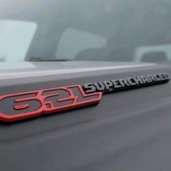
 I always drive in Sport mode. With more driving, I am finding the initial response when accelerating is much quicker now🖕 Lou
-
-
GM-Trucks.com Clubs
-

Black Truck Club
Open Club · 612 members
-

White Truck Club
Open Club · 380 members
-

Canadian Owners Club
Open Club · 282 members
-

Red Truck Club
Open Club · 157 members
-

diesel 3.0
Open Club · 281 members
-

Texas Owner's Group
Open Club · 371 members
-

NorthSky Blue Club
Open Club · 118 members
-

Midwest Owner's Group
Open Club · 213 members
-

2015 Custom Sport Club
Open Club · 5 members
-

GM Snow Plowing Club HD
Closed Club · 14 members
-
-
Popular Contributors
-
.thumb.JPG.2c573de60d3a3a4407c7d92298db46dd.JPG)


Recommended Posts
Create an account or sign in to comment
You need to be a member in order to leave a comment
Create an account
Sign up for a new account in our community. It's easy!
Register a new accountSign in
Already have an account? Sign in here.
Sign In Now