
-
Recently Browsing 0 members
- No registered users viewing this page.
-
Forum Statistics
250.5k
Total Topics2.7m
Total Posts -
Member Statistics
342,889
Total Members8,960
Most Online
-
Who's Online 18 Members, 1 Anonymous, 842 Guests (See full list)
-
Latest Articles
-
Posts
-
 When most people look at GM's EV strategy, they think it was dumb. Obviously, duh? In hindsight, there was significant financial risk in becoming obsolete if GM didn't go all-in, like a lot of automakers. Had the EV market taken off, GM would have been left defenseless. Not all of their $10.9B was lost. Only a part of that was sunk costs like supplier penalties and retooling for EV's they canceled or never made. A sizable chunk of that was R&D and intellectual property which is still in their back pocket for future EVs. GM hedged the risk but overspent, but then they pivoted and focused on their bread and butter. Not only did GM still have the financial prowess to do that, they've done so successfully. It shows a lot of resilience and the market rewarded it.
 -
By Bloody Marty · Posted
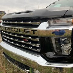
Here is my '26 with just the torsions adjusted up approximately 1.5", aligned & good to go. Ride is somewhat stiffer but level & looks great IMO. Tires are Nitto Trail Grappler MT's 35 x 12.5 x 20 on stock rims. Truck has about 14,500 miles -

By asilverblazer · Posted
Are ALL injectors losing ground or just #7. Sounds like a wiring problem to me. -
 Thank you! Helpful and assuring! For others on this forum, it would be helpful for them to know if they have AFM/DFM present - and on which TurboMax model variants/years/ or VIN# indicator letter? Thanks Bill
 -
By asilverblazer · Posted
Agree 100% the buy backs are a prop to the stock price, in showing confidence, generating demand and thus inflating the price. The problem is the over focus on the shareholders to the detriment of the customer - the customer will only take so much pressure before they switch brands - and rarely switch back. Eventually, no customers means no sales, what value to shareholders is there then? Which leads back to the EV strategy, EVERYONE KNEW the EV customers didn't exist yet, but they went ahead anyway because the shareholders wanted it (Stock price increases at each press release), the release of the Hummer proved it (again, if you go back to the ELR coupe), but GM kept doggedly moving ahead with Cadillacs all electric future, Blazer EV, Equinox EV and again the ONLY EV with any kind of momentum was an on again off again mess. Further why was the success of the Volt/Bolt compared to the failure(s) of the Hummer/ELR not considered? Premium EVs weren't the answer. Cadillac is now in one of its weakest positions in decades, resurrecting aged platforms to rush back into a market the customers never left and are now searching other brands for. These are OBVIOUS MISTAKES (plus many others outside EV) that cost BILLIONS, people should have been fired, likely many people. GMs value as a brand to me exists only in what the assets could be sold for, because they obviously can't lead the industry.
-
-
GM-Trucks.com Clubs
-

Black Truck Club
Open Club · 612 members
-

White Truck Club
Open Club · 380 members
-

Canadian Owners Club
Open Club · 282 members
-

Red Truck Club
Open Club · 157 members
-

diesel 3.0
Open Club · 281 members
-

Texas Owner's Group
Open Club · 371 members
-

NorthSky Blue Club
Open Club · 118 members
-

Midwest Owner's Group
Open Club · 213 members
-

2015 Custom Sport Club
Open Club · 5 members
-

GM Snow Plowing Club HD
Closed Club · 14 members
-
-
Popular Contributors
-
.thumb.JPG.2c573de60d3a3a4407c7d92298db46dd.JPG)


Recommended Posts
Create an account or sign in to comment
You need to be a member in order to leave a comment
Create an account
Sign up for a new account in our community. It's easy!
Register a new accountSign in
Already have an account? Sign in here.
Sign In Now