-
Recently Browsing 0 members
- No registered users viewing this page.
-
Forum Statistics
250.5k
Total Topics2.7m
Total Posts -
Member Statistics
342,896
Total Members8,960
Most Online
-
Who's Online 10 Members, 0 Anonymous, 1,282 Guests (See full list)
-
Latest Articles
-
Posts
-
By JimCost2014 · Posted
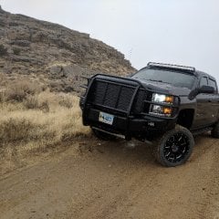
If what you are doing works, keep doing it: 4LO (Four-Wheel Drive Low) should only be used in extreme low-speed, high-torque situations such as deep mud, heavy snow, steep rock crawling, or extreme inclines/declines, and you must follow the correct engagement procedure to avoid drivetrain damage. Intended Use Cases Deep mud or snow where traction is extremely poor and you need maximum torque to get unstuck Trucks Only+1. Rock crawling on steep, uneven terrain forum.fullsizechevy.com+1. Extreme inclines or declines where you need to control speed and maintain traction solutionsphere.blog. Heavy towing in low-traction conditions (e.g., deep sand, ice) carclubsusa.com. -
 Hi, I work a steep boat landing that has patchy blacktop going down the hill and soft sand/gravel at the bottom. Due to low water levels, it's not always possible reach the blacktop. I've had to help several people get out this year already and with fall coming, I'm anticipating more. I always use 4L. There was a gentleman there today with a 2500 HD (actually 2 - him and his son both have them) and they were trying to get his son's wake boat out. This gentleman swears that you should use 4H in the soft gravel. Says he was a farmer and you always use higher gear when stuck. I was wonder what your thoughts on this are? If I'm wrong, it would be good to find out before things get busy.
 -

By Bill Lemmond · Posted
Looking for feedback from users of roll up aluminum slat bed covers who have had it for more than 3 years. I prefer the aluminum slat style over supported vinyl covers due to security and the capacity to support a light load. The slight loss of bed opening when rolled up is not an issue. Presently have BAK Revolver the "industrial grade vinyl overlay" on mine is shrinking & coming loose at the rear and on both sides in addition to cracking at some of the folding joints. Truck lives outdoors in NC latitude. Can't justify the steep price to replace it with another one if that's the expected lifespan. Do you have a better alternative? -
By Bill Lemmond · Posted
Thanks, your last sentence is the root of my problem, outdoors truck and southern latitude = UV overload. Looking at replacing with Rough Country powder coated aluminum slat roll up model. -
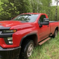
 I’m looking at putting a lift in my 2024 gmc sierra 1500 elevation trim, has anyone had any luck with fitting a bigger tire under the rear for a spare?? Was gonna go with a 4 inch zone lift Also what wheel and tire size setup are you all running? Wondering if I can get away with keeping around the stock size a 33 inch, and just get some new wheels to have enough back spacing then I can just keep my original spare tire I have under the truck now.
-
-
GM-Trucks.com Clubs
-

Black Truck Club
Open Club · 612 members
-

White Truck Club
Open Club · 380 members
-

Canadian Owners Club
Open Club · 282 members
-

Red Truck Club
Open Club · 157 members
-

diesel 3.0
Open Club · 281 members
-

Texas Owner's Group
Open Club · 371 members
-

NorthSky Blue Club
Open Club · 118 members
-

Midwest Owner's Group
Open Club · 213 members
-

2015 Custom Sport Club
Open Club · 5 members
-

GM Snow Plowing Club HD
Closed Club · 14 members
-
-
Popular Contributors
-
.thumb.JPG.2c573de60d3a3a4407c7d92298db46dd.JPG)


Recommended Posts
Create an account or sign in to comment
You need to be a member in order to leave a comment
Create an account
Sign up for a new account in our community. It's easy!
Register a new accountSign in
Already have an account? Sign in here.
Sign In Now