-
Recently Browsing 0 members
- No registered users viewing this page.
-
Forum Statistics
250.5k
Total Topics2.7m
Total Posts -
Member Statistics
342,892
Total Members8,960
Most Online
-
Who's Online 5 Members, 0 Anonymous, 631 Guests (See full list)
-
Latest Articles
-
Posts
-
.thumb.JPG.2c573de60d3a3a4407c7d92298db46dd.JPG)
By Grumpy Bear · Posted
Let me introduce you to my Mirage 1.2 three pot with a CVT! Know what a Mirage can pass a Hell Cat Hemi can't? 😉 -
 I spent a fair amount of time in the 2018-2024 versions. Had two different Equinox and a Terrain as loaners when my Silverado was down (regularly). I actually really liked them. Very comfortable. Efficient. The GMC was a SLT and had a reasonably nice interior too. And I’ve seen a lot of them go high miles with the 1.5. Unfortunately for me I’d have to go 2.0 because the 1.5 is SO SLOW. I know it’s not a performance vehicle anyway but I just can’t drive that much of a dog. The Malibu I had with the same motor wasn’t much peppier. These tiny engines just can’t move these bigger cars very well.
 -

By xdieselmechanic · Posted
All injectors are loosing the ground side from the pcm even with all injectors unplugg there is still.no ground pulse on any injector -
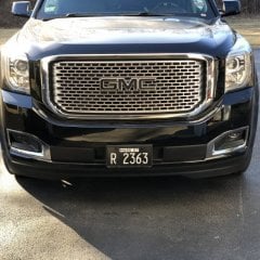
 Picked up the new ride earlier today.
 -

-
-
GM-Trucks.com Clubs
-

Black Truck Club
Open Club · 612 members
-

White Truck Club
Open Club · 380 members
-

Canadian Owners Club
Open Club · 282 members
-

Red Truck Club
Open Club · 157 members
-

diesel 3.0
Open Club · 281 members
-

Texas Owner's Group
Open Club · 371 members
-

NorthSky Blue Club
Open Club · 118 members
-

Midwest Owner's Group
Open Club · 213 members
-

2015 Custom Sport Club
Open Club · 5 members
-

GM Snow Plowing Club HD
Closed Club · 14 members
-
-
Popular Contributors
-


Recommended Posts
Create an account or sign in to comment
You need to be a member in order to leave a comment
Create an account
Sign up for a new account in our community. It's easy!
Register a new accountSign in
Already have an account? Sign in here.
Sign In Now