

-
Similar Content
-
Here is the video of the knocking noise from my 2025 Suburban 5.3 V8 L84
By George Yorkshire,
- Knock knock
- sounds
- (and 9 more)
- 1 reply
- 755 views
-
2025 Suburban 5.3L - Lifter or Bottom End Failure? 11k Miles of Dealership Gaslighting - Seeking Advice
By George Yorkshire,
- knock
- Knock knock
- (and 1 more)
- 6 replies
- 1,639 views
-
- 4 replies
- 2,919 views
-
- 2 replies
- 3,483 views
-
- 0 replies
- 3,616 views
-
-
Recently Browsing 0 members
- No registered users viewing this page.
-
Forum Statistics
250.5k
Total Topics2.7m
Total Posts -
Member Statistics
342,915
Total Members8,960
Most Online
-
Who's Online 8 Members, 0 Anonymous, 1,254 Guests (See full list)





-
Latest Articles
-
Posts
-
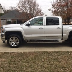 I have the same running boards on my truck and I do agree they are bulky. I also find myself stepping over them when getting in and out of the truck. Besides providing protection to the rocker panels, they aren't very useful. I will be replacing them soon with the Amp Powersteps.
 -
By ChristopherDobson · Posted
Monthly payment is only part of the equation. With today's prices and interest rates, I'd look at the total monthly cost: payment, insurance, registration, fuel, maintenance, and expected repairs. A vehicle that fits comfortably into your budget is usually the better choice than stretching for a higher trim. I've also kept my vehicles longer over the past few years. New cars have gotten expensive enough that driving one for 10+ years, while staying on top of maintenance, often ends up being the most cost-effective approach. -
.thumb.JPG.2c573de60d3a3a4407c7d92298db46dd.JPG)
By Grumpy Bear · Posted
10 Ford and Chevy engines proven to reach 300,000 miles You may note a common 3K OCI on this list of gas motors. I skipped over the diesels. Dh'O. -
 Thanks newdude! By the time manual selection is needed, I'm probably too much of a control-freak to depend on the transmission sensing braking to activate automatic downshifting. I would be anticipating the situation and already be manually downshifting. This truck replaced a 2004.5 LLY diesel with the Allison 5-speed. Putting it in T/H made noticeable differences (when the torque converter locked, upshift points, downshift behavior). On this 2024 gasser with the 10L1000 I haven't been able to detect much, if any, difference. Ok, I can never tell now when the torque converter locks up. But I also don't notice differences in shifting. For downhills, I've probably already manually downshifted by then anyway. Since it's also more awkward (than the 2004.5) to engage/disengage I don't even bother. Or maybe it doesn't really matter with just a 3k lb. camper in the bed? Thanks also for the list of reasons the charging system might select various voltages. However, what I am seeing doesn't fall into any of those categories. It very definitely, and very consistently, rises after coasting/braking. Maybe not immediately, but not very long after coasting/braking. Very consistently drops voltage when no longer coasting/braking. It might also be interacting with the camper battery charging (I might disconnect the camper and see if it changes the charging behavior). I also need to recheck turning on headlights for when I want to force it to charge the camper. Another JR, in June I converted the camper to LiFePO4. Since it's not a good idea to try to charge lithiums directly using truck, I installed a Victron Orion XS DC-DC charger (which BTW is AMAZING!!). Being cheap, I only had to buy that one item (besides the battery, of course) to do the conversion. The camper OEM 120v battery charger (only 19 years old and works perfectly) and the truck feed the input to the DC-DC charger (not at the same time). But I didn't want the camper charger feeding back to the truck so I kept the old separator. I considered replacing the separator with a 30amp diode but that means more work and might add another 1/2 volt drop. One thing that surprised me was the voltage drop over the long 10awg wire run, so I can only charge smoothly at 8 amps (because the DC-DC charger is completely configurable). Another reason I don't want an added voltage drop with the diode. I might also be a little lazy but all this work is being done under the sink with a small cabinet opening.
 -
 apparently CA smog is (or at least was) checking that the vehicle is using the oem and/or a ca smog approved tune, so I expect you'll fail inspection doing it.
-
-
GM-Trucks.com Clubs
-

Black Truck Club
Open Club · 613 members
-

White Truck Club
Open Club · 380 members
-

Canadian Owners Club
Open Club · 282 members
-

Red Truck Club
Open Club · 158 members
-

diesel 3.0
Open Club · 281 members
-

Texas Owner's Group
Open Club · 371 members
-

NorthSky Blue Club
Open Club · 118 members
-

Midwest Owner's Group
Open Club · 213 members
-

2015 Custom Sport Club
Open Club · 5 members
-

GM Snow Plowing Club HD
Closed Club · 14 members
-
-
Popular Contributors
-




Recommended Posts
Create an account or sign in to comment
You need to be a member in order to leave a comment
Create an account
Sign up for a new account in our community. It's easy!
Register a new accountSign in
Already have an account? Sign in here.
Sign In Now